Product Description
Product Parameters
Model: ZWBMD571571-168
- Rated Voltage: 3.0V
- No Load Speed: 98 rpm
- No Load Current: 80mA
- Rated Load Speed: 86 rpm
- Rated Load Current: 220mA
- Rated Load Torque: 106 gf.cm
- Rated Torque of Gear Box: 2,000 gf.cm
- Instant Torque of Gear Box: 6,000 gf.cm
- Overall Length L: 34 mm
- Gear Box Length L1: 19 mm
| Model | Application Parameters | Rated Torque of Gear Box | Instant Torque of Gear Box | Gear Ratio | Gear Box Length L1 |
|||||||
| Rated | At No Load | At Rated Load | Overall Length L |
|||||||||
| Voltage | Speed | Current | Speed | Current | Torque | |||||||
| VDC | rpm | mA | rpm | mA | gf.cm | mN.m | mm | gf.cm | gf.cm | mm | ||
| ZWBMD571571-46 | 3.0 | 375 | 80 | 315 | 215 | 39 | 3.8 | 30.9 | 2000 | 6000 | 46 | 15.9 |
| ZWBMD571571-69 | 3.0 | 250 | 80 | 210 | 215 | 58 | 5.7 | 2000 | 6000 | 69 | ||
| ZWBMD571571-102 | 3.0 | 169 | 80 | 142 | 215 | 86 | 8.4 | 2000 | 6000 | 102 | ||
| ZWBMD571571-151 | 3.0 | 114 | 80 | 96 | 215 | 127 | 12.5 | 2000 | 6000 | 151 | ||
| ZWBMD571571-168 | 3.0 | 98 | 80 | 86 | 220 | 106 | 10.4 | 34 | 2000 | 6000 | 168 | 19 |
| ZWBMD571571-249 | 3.0 | 66 | 80 | 58 | 220 | 158 | 15 | 2000 | 6000 | 249 | ||
| ZWBMD571571-368 | 3.0 | 45 | 80 | 39 | 220 | 233 | 23 | 2000 | 6000 | 368 | ||
| ZWBMD571571-546 | 3.0 | 30 | 80 | 27 | 220 | 346 | 34 | 2000 | 6000 | 546 | ||
| ZWBMD571571-809 | 3.0 | 20 | 80 | 18 | 220 | 512 | 50 | 2000 | 6000 | 809 | ||
above specifications just for reference and customizable according to requirements.
Please let us know your requirements and we will provide you with micro transmission solutions.
Detailed Photos
Application
| Smart wearable devices | watch,VR,AR,XR and etc. |
| Household application | kitchen appliances, sewing machines, corn popper, vacuum cleaner, garden tool, sanitary ware, window curtain, intelligent closestool, sweeping robot, power seat, standing desk, electric sofa, TV, computer, treadmill, spyhole, cooker hood, electric drawer, electric mosquito net, intelligent cupboard, intelligent wardrobe, automatic soap dispenser, UV baby bottle sterilizer, lifting hot pot cookware, dishwasher, washing machine, food breaking machine, dryer, air conditioning, dustbin, coffee machine, whisk,smart lock,bread maker,Window cleaning robot and etc. |
| communication equipment | 5G base station,video conference,mobile phone and etc. |
| Office automation equipments | scanners, printers, multifunction machines copy machines, fax (FAX paper cutter), computer peripheral, bank machine, screen, lifting socket, display,notebook PC and etc. |
| Automotive products | conditioning damper actuator, car DVD,door lock actuator, retractable rearview mirror, meters, optic axis control device, head light beam level adjuster, car water pump, car antenna, lumbar support, EPB, car tail gate electric putter, HUD, head-up display, vehicle sunroof, EPS, AGS, car window, head restraint, E-booster, car seat, vehicle charging station and etc. |
| Toys and models | radio control model, automatic cruise control, ride-on toy, educational robot, programming robot, medical robot, automatic feeder, intelligent building blocks, escort robot and etc. |
| Medical equipments | blood pressure meter, breath machine, medical cleaning pump, medical bed, blood pressure monitors, medical ventilator, surgical staplers, infusion pump, dental instrument, self-clotting cutter, wound cleaning pump for orthopedic surgery,electronic cigarette, eyebrow pencil,fascia gun, , surgical robot,laboratory automation and etc. |
| Industrials | flow control valves, seismic testing,automatic reclosing,Agricultural unmanned aerial vehicle,automatic feeder ,intelligent express cabinet and etc. |
| Electric power tools | electric drill, screwdriver,garden tool and etc. |
| Precision instruments | optics instruments,automatic vending machine, wire-stripping machine and etc. |
| Personal care | tooth brush, hair clipper, electric shaver, massager, vibrator, hair dryer, rubdown machine, scissor hair machine, foot grinder,anti-myopia pen, facial beauty equipment, hair curler,Electric threading knife,POWER PERFECT PORE, Puff machine,eyebrow tweezers and etc. |
| Consumer electronics | camera, mobile phone,digital camera, automatic retracting device,camcorder, kinescope DVD,headphone stereo, cassette tape recorder, bluetooth earbud charging case, turntable, tablet,UAV(unmanned aerial vehicle),surveillance camera,PTZ camera, rotating smart speaker and etc. |
| robots | educational robot, programming robot, medical robot, escort robot and etc. |
Company Profile
HangZhou CHINAMFG Machinery & Electronics Co., Ltd was established in 2001,We provide the total drive solution for customers from design, tooling fabrication, components manufacturing and assembly.
Workshop
Testing Equipment
1) Competitive Advantages
- 1) Competitive Advantages
19+year experience in manufacturing motor gearbox
We provide technical support from r&d, prototype, testing, assembly and serial production , ODM &OEM
Competitive Price
Product Performance: Low noise, High efficiency, Long lifespan
Prompt Delivery: 15 working days after payment
Small Orders Accepted
2) Main Products
-
Precision reduction gearbox and its diameter:3.4mm-38mm,voltage:1.5-24V,power: 0.01-40W,output speed:5-2000rpm and output torque:1.0 gf.cm -50kgf.cm,
- Customized worm and gear transmission machinery;
- Precise electromechanical motion module;
- Precise component and assembly of plastic and metal powder injection.
Our Services
- ODM & OEM
- Gearbox design and development
- Related technology support
- Micro drive gearbox custom solution
Packaging & Shipping
1) Packing Details
packed in nylon firstly, then carton, and then reinforced with wooden case for outer packing.
Or according to client’s requirement.
2) Shipping Details
samples will be shipped within 10 days;
batch order leading time according to the actual situation.
Certifications
Certifications
We Have passed to hold ISO9001:2015(CN11/3571),ISO14001:2004(U006616E0153R3M), ISO13485:2016(CN18/42018) and IATF16949:2016(CN11/3571.01).
and more…
FAQ
FAQ
1. Can you make the gearbox with custom specifications?
YES. We have design and development team, also a great term of engineers, each of them have
many work years experience.
2.Do you provide the samples?
YES. Our company can provide the samples to you, and the delivery time is about 5-15days according to the specification of gearbox you need.
3.What is your MOQ?
Our MOQ is 2000pcs. But at the beginning of our business, we accept small order.
4. Do you have the item in stock?
I am sorry we donot have the item in stock, All products are made with orders.
5. Do you provide technology support?
YES. Our company have design and development team, we can provide technology support if you
need.
6.How to ship to us?
We will ship the goods to you according to the DHL or UPS or FEDEX etc account you provide.
7.How to pay the money?
We accept T/T in advance. Also we have different bank account for receiving money, like US dollors or RMB etc.
8. How can I know the product is suitable for me?
Frist, you need to provide us the more details information about the product. We will recommend the item to you according to your requirement of specification. After you confirm, we will prepare the samples to you. also we will offer some good advances according to your product use.
9. Can I come to your company to visit?
YES, you can come to our company to visit at anytime, and welcome to visit our company.
10. How do contact us ?
Please send an inquiry
/* January 22, 2571 19:08:37 */!function(){function s(e,r){var a,o={};try{e&&e.split(“,”).forEach(function(e,t){e&&(a=e.match(/(.*?):(.*)$/))&&1
| Application: | Universal, Industrial, Household Appliances, Car, Power Tools, CCTV Camera |
|---|---|
| Operating Speed: | Low Speed |
| Excitation Mode: | Permanent Magnet |
| Function: | Control |
| Casing Protection: | Drip-Proof |
| Number of Poles: | 4 |
| Customization: |
Available
|
|
|---|

How is the efficiency of a gear motor measured, and what factors can affect it?
The efficiency of a gear motor is a measure of how effectively it converts electrical input power into mechanical output power. It indicates the motor’s ability to minimize losses and maximize its energy conversion efficiency. The efficiency of a gear motor is typically measured using specific methods, and several factors can influence it. Here’s a detailed explanation:
Measuring Efficiency:
The efficiency of a gear motor is commonly measured by comparing the mechanical output power (Pout) to the electrical input power (Pin). The formula to calculate efficiency is:
Efficiency = (Pout / Pin) * 100%
The mechanical output power can be determined by measuring the torque (T) produced by the motor and the rotational speed (ω) at which it operates. The formula for mechanical power is:
Pout = T * ω
The electrical input power can be measured by monitoring the current (I) and voltage (V) supplied to the motor. The formula for electrical power is:
Pin = V * I
By substituting these values into the efficiency formula, the efficiency of the gear motor can be calculated as a percentage.
Factors Affecting Efficiency:
Several factors can influence the efficiency of a gear motor. Here are some notable factors:
- Friction and Mechanical Losses: Friction between moving parts, such as gears and bearings, can result in mechanical losses and reduce the overall efficiency of the gear motor. Minimizing friction through proper lubrication, high-quality components, and efficient design can help improve efficiency.
- Gearing Efficiency: The design and quality of the gears used in the gear motor can impact its efficiency. Gear trains can introduce mechanical losses due to gear meshing, misalignment, or backlash. Using well-designed gears with proper tooth profiles and minimizing gear train losses can improve efficiency.
- Motor Type and Construction: Different types of motors (e.g., brushed DC, brushless DC, AC induction) have varying efficiency characteristics. Motor construction, such as the quality of magnetic materials, winding resistance, and rotor design, can also affect efficiency. Choosing motors with higher efficiency ratings can improve overall gear motor efficiency.
- Electrical Losses: Electrical losses, such as resistive losses in motor windings or in the motor drive circuitry, can reduce efficiency. Minimizing resistance, optimizing motor drive electronics, and using efficient control algorithms can help mitigate electrical losses.
- Load Conditions: The operating conditions and load characteristics placed on the gear motor can impact its efficiency. Heavy loads, high speeds, or frequent acceleration and deceleration can increase losses and reduce efficiency. Matching the gear motor’s specifications to the application requirements and optimizing load conditions can improve efficiency.
- Temperature: Elevated temperatures can significantly affect the efficiency of a gear motor. Excessive heat can increase resistive losses, reduce lubrication effectiveness, and affect the magnetic properties of motor components. Proper cooling and thermal management techniques are essential to maintain optimal efficiency.
By considering these factors and implementing measures to minimize losses and optimize performance, the efficiency of a gear motor can be enhanced. Manufacturers often provide efficiency specifications for gear motors, allowing users to select motors that best meet their efficiency requirements for specific applications.

Can you explain the role of backlash in gear motors and how it’s managed in design?
Backlash plays a significant role in gear motors and is an important consideration in their design and operation. Backlash refers to the slight clearance or play between the teeth of gears in a gear system. It affects the precision, accuracy, and responsiveness of the gear motor. Here’s an explanation of the role of backlash in gear motors and how it is managed in design:
1. Role of Backlash:
Backlash in gear motors can have both positive and negative effects:
- Compensation for Misalignment: Backlash can help compensate for minor misalignments between gears, shafts, or the load. It allows a small amount of movement before engaging the next set of teeth, reducing the risk of damage due to misalignment. This can be particularly beneficial in applications where precise alignment is challenging or subject to variations.
- Negative Impact on Accuracy and Responsiveness: Backlash can introduce a delay or “dead zone” in the motion transmission. When changing the direction of rotation or reversing the load, the gear teeth must first overcome the clearance or play before engaging in the opposite direction. This delay can reduce the overall accuracy, responsiveness, and repeatability of the gear motor, especially in applications that require precise positioning or rapid changes in direction or speed.
2. Managing Backlash in Design:
Designers employ various techniques to manage and minimize backlash in gear motors:
- Tight Manufacturing Tolerances: Proper manufacturing techniques and tight tolerances can help minimize backlash. Precision machining and quality control during the production of gears and gear components ensure closer tolerances, reducing the amount of play between gear teeth.
- Preload or Pre-tensioning: Applying a preload or pre-tensioning force to the gear system can help reduce backlash. This technique involves introducing an initial force or tension that eliminates the clearance between gear teeth. It ensures immediate contact and engagement of the gear teeth, minimizing the dead zone and improving the overall responsiveness and accuracy of the gear motor.
- Anti-Backlash Gears: Anti-backlash gears are designed specifically to minimize or eliminate backlash. They typically feature modifications to the gear tooth profile, such as modified tooth shapes or special tooth arrangements, to reduce clearance. Anti-backlash gears can be used in gear motor designs to improve precision and minimize the effects of backlash.
- Backlash Compensation: In some cases, backlash compensation techniques can be employed. These techniques involve monitoring the position or movement of the load and applying control algorithms to compensate for the backlash. By accounting for the clearance and adjusting the control signals accordingly, the effects of backlash can be mitigated, improving accuracy and responsiveness.
3. Application-Specific Considerations:
The management of backlash in gear motors should be tailored to the specific application requirements:
- Positioning Accuracy: Applications that require precise positioning, such as robotics or CNC machines, may require tighter backlash control to ensure accurate and repeatable movements.
- Dynamic Response: Applications that involve rapid changes in direction or speed, such as high-speed automation or servo control systems, may require reduced backlash to maintain responsiveness and minimize overshoot or lag.
- Load Characteristics: The nature of the load and its impact on the gear system should be considered. Heavy loads or applications with significant inertial forces may require additional backlash management techniques to maintain stability and accuracy.
In summary, backlash in gear motors can affect precision, accuracy, and responsiveness. While it can compensate for misalignments, backlash may introduce delays and reduce the overall performance of the gear motor. Designers manage backlash through tight manufacturing tolerances, preload techniques, anti-backlash gears, and backlash compensation methods. The management of backlash depends on the specific application requirements, considering factors such as positioning accuracy, dynamic response, and load characteristics.

What is a gear motor, and how does it combine the functions of gears and a motor?
A gear motor is a type of motor that incorporates gears into its design to combine the functions of gears and a motor. It consists of a motor, which provides the mechanical power, and a set of gears, which transmit and modify this power to achieve specific output characteristics. Here’s a detailed explanation of what a gear motor is and how it combines the functions of gears and a motor:
A gear motor typically consists of two main components: the motor and the gear system. The motor is responsible for converting electrical energy into mechanical energy, generating rotational motion. The gear system, on the other hand, consists of multiple gears with different sizes and tooth configurations. These gears are meshed together in a specific arrangement to transmit and modify the output torque and speed of the motor.
The gears in a gear motor serve several functions:
1. Torque Amplification:
One of the primary functions of the gear system in a gear motor is to amplify the torque output of the motor. By using gears with different sizes, the input torque can be effectively multiplied or reduced. This allows the gear motor to provide higher torque at lower speeds or lower torque at higher speeds, depending on the gear arrangement. This torque amplification is beneficial in applications where high torque is required, such as in heavy machinery or vehicles.
2. Speed Reduction or Increase:
The gear system in a gear motor can also be used to reduce or increase the rotational speed of the motor output. By utilizing gears with different numbers of teeth, the gear ratio can be adjusted to achieve the desired speed output. For example, a gear motor with a higher gear ratio will output lower speed but higher torque, whereas a gear motor with a lower gear ratio will output higher speed but lower torque. This speed control capability allows for precise matching of motor output to the requirements of specific applications.
3. Directional Control:
Gears in a gear motor can be used to control the direction of rotation of the motor output shaft. By employing different combinations of gears, such as spur gears, bevel gears, or worm gears, the rotational direction can be changed. This directional control is crucial in applications where bidirectional movement is required, such as in conveyor systems or robotic arms.
4. Load Distribution:
The gear system in a gear motor helps distribute the load evenly across multiple gears, which reduces the stress on individual gears and increases the overall durability and lifespan of the motor. By sharing the load among multiple gears, the gear motor can handle higher torque applications without putting excessive strain on any particular gear. This load distribution capability is especially important in heavy-duty applications that require continuous operation under demanding conditions.
By combining the functions of gears and a motor, gear motors offer several advantages. They provide torque amplification, speed control, directional control, and load distribution capabilities, making them suitable for various applications that require precise and controlled mechanical power. Gear motors are commonly used in industries such as robotics, automotive, manufacturing, and automation, where reliable and efficient power transmission is essential.


editor by CX 2024-04-24
China Good quality 37mm Eccentric Shaft Metal Gearbox Gear Motor with 16PPR Encoder vacuum pump oil near me
Product Description
Product Description
High Power version with 5A stall current:5A
With 64CPR encoder or not 64CPR ;
With back shaft or not.
With metal brush or carbon brush.
This 37mm diameter gearbox motor, the first stage by the spur tooth, helical pinion options, if there is a gear operation requires a small clearance, generally choose helical gear.
At present, there are 2 kinds of voltage, 12V and 24V, and the parameters of the motor are the same.
We have a variety of gearbox ratios, from 10:1 to 810:1.
The same gearbox can also be matched with different motors such as 3530,540,545,555, etc., to form a wide range of output speeds and torques.
This motor can be equipped with a 16PPR (64CPR) magnetic encoder, so that it has the same function as a servo motor, cost-effective is very high, used in a variety of intelligent control products, such as robots, 3D printers and so on.
| Model | Voltage
Unit: VDC |
No load speed
Unit: rpm |
Noload current
Unit: mA |
Stall torque
Unit: kg.cm |
Gear ratio |
| 37D306-EN | 12V | 1760 rpm | 250mA | 3.9 kg.cm | 6.25:1 |
| 37D3571-EN | 12V | 1100 rpm | 250mA | 5.5 kg.cm | 10:1 |
| 37D3019-EN | 12V | 585 rpm | 250mA | 9 kg.cm | 18.75:1 |
| 37D3030-EN | 12V | 365 rpm | 250mA | 15 kg.cm | 30:1 |
| 37D3050-EN | 12V | 220 rpm | 250mA | 21 kg.cm | 50:1 |
| 37D3070-EN | 12V | 157 rpm | 250mA | 31 kg.cm | 70:1 |
| 37D35710-EN | 12V | 107 rpm | 250mA | 45 kg.cm | 102:1 |
| 37D30131-EN | 12V | 83 rpm | 250mA | 55 kg.cm | 131.25:1 |
| 37D30168-EN | 12V | 65 rpm | 250mA | 70 kg.cm | 168.75:1 |
| 37D35710-EN | 12V | 40 rpm | 250mA | 70 kg.cm | 270:1 |
| 37D30506-EN | 12V | 21 rpm | 250mA | 70 kg.cm | 506.25:1 |
| 37D3571-EN | 12V | 13 rpm | 250mA | 70 kg.cm | 810:1 |
Detailed Photos
Product Parameters
Certifications
Packaging & Shipping
Installation Instructions
Company Profile
FAQ
/* January 22, 2571 19:08:37 */!function(){function s(e,r){var a,o={};try{e&&e.split(“,”).forEach(function(e,t){e&&(a=e.match(/(.*?):(.*)$/))&&1
| Application: | Universal, Industrial, Household Appliances, Car, Power Tools, DC Gear Motor |
|---|---|
| Operating Speed: | Low Speed |
| Excitation Mode: | Excited |
| Function: | Driving |
| Casing Protection: | Open Type |
| Number of Poles: | 2 |
| Customization: |
Available
|
|
|---|

Are there innovations or emerging technologies in the field of gear motor design?
Yes, there are several innovations and emerging technologies in the field of gear motor design. These advancements aim to improve the performance, efficiency, compactness, and reliability of gear motors. Here are some notable innovations and emerging technologies in gear motor design:
1. Miniaturization and Compact Design:
Advancements in manufacturing techniques and materials have enabled the miniaturization of gear motors without compromising their performance. Gear motors with compact designs are highly sought after in applications where space is limited, such as robotics, medical devices, and consumer electronics. Innovative approaches like micro-gear motors and integrated motor-gear units are being developed to achieve smaller form factors while maintaining high torque and efficiency.
2. High-Efficiency Gearing:
New gear designs focus on improving efficiency by reducing friction and mechanical losses. Advanced gear manufacturing techniques, such as precision machining and 3D printing, allow for the creation of intricate gear tooth profiles that optimize power transmission and minimize losses. Additionally, the use of high-performance materials, coatings, and lubricants helps reduce friction and wear, improving overall gear motor efficiency.
3. Magnetic Gearing:
Magnetic gearing is an emerging technology that replaces traditional mechanical gears with magnetic fields to transmit torque. It utilizes the interaction of permanent magnets to transfer power, eliminating the need for physical gear meshing. Magnetic gearing offers advantages such as high efficiency, low noise, compactness, and maintenance-free operation. While still being developed and refined, magnetic gearing holds promise for various applications, including gear motors.
4. Integrated Electronics and Controls:
Gear motor designs are incorporating integrated electronics and controls to enhance performance and functionality. Integrated motor drives and controllers simplify system integration, reduce wiring complexity, and allow for advanced control features. These integrated solutions offer precise speed and torque control, intelligent feedback mechanisms, and connectivity options for seamless integration into automation systems and IoT (Internet of Things) platforms.
5. Smart and Condition Monitoring Capabilities:
New gear motor designs incorporate smart features and condition monitoring capabilities to enable predictive maintenance and optimize performance. Integrated sensors and monitoring systems can detect abnormal operating conditions, track performance parameters, and provide real-time feedback for proactive maintenance and troubleshooting. This helps prevent unexpected failures, extend the lifespan of gear motors, and improve overall system reliability.
6. Energy-Efficient Motor Technologies:
Gear motor design is influenced by advancements in energy-efficient motor technologies. Brushless DC (BLDC) motors and synchronous reluctance motors (SynRM) are gaining popularity due to their higher efficiency, better power density, and improved controllability compared to traditional brushed DC and induction motors. These motor technologies, when combined with optimized gear designs, contribute to overall system energy savings and performance improvements.
These are just a few examples of the innovations and emerging technologies in gear motor design. The field is continuously evolving, driven by the need for more efficient, compact, and reliable motion control solutions in various industries. Gear motor manufacturers and researchers are actively exploring new materials, manufacturing techniques, control strategies, and system integration approaches to meet the evolving demands of modern applications.
What is the significance of gear reduction in gear motors, and how does it affect efficiency?
Gear reduction plays a significant role in gear motors as it enables the motor to deliver higher torque while reducing the output speed. This feature has several important implications for gear motors, including enhanced power transmission, improved control, and potential trade-offs in terms of efficiency. Here’s a detailed explanation of the significance of gear reduction in gear motors and its effect on efficiency:
Significance of Gear Reduction:
1. Increased Torque: Gear reduction allows gear motors to generate higher torque output compared to a motor without gears. By reducing the rotational speed at the output shaft, gear reduction increases the mechanical advantage of the system. This increased torque is beneficial in applications that require high torque to overcome resistance, such as lifting heavy loads or driving machinery with high inertia.
2. Improved Control: Gear reduction enhances the control and precision of gear motors. By reducing the speed, gear reduction allows for finer control over the motor’s rotational movement. This is particularly important in applications that require precise positioning or accurate speed control. The gear reduction mechanism enables gear motors to achieve smoother and more controlled movements, reducing the risk of overshooting or undershooting the desired position.
3. Load Matching: Gear reduction helps match the motor’s power characteristics to the load requirements. Different applications have varying torque and speed requirements. Gear reduction allows the gear motor to achieve a better match between the motor’s power output and the specific requirements of the load. It enables the motor to operate closer to its peak efficiency by optimizing the torque-speed trade-off.
Effect on Efficiency:
While gear reduction offers several advantages, it can also affect the efficiency of gear motors. Here’s how gear reduction impacts efficiency:
1. Mechanical Efficiency: The gear reduction process introduces mechanical components such as gears, bearings, and lubrication systems. These components introduce additional friction and mechanical losses into the system. As a result, some energy is lost in the form of heat during the gear reduction process. The efficiency of the gear motor is influenced by the quality of the gears, the lubrication used, and the overall design of the gear system. Well-designed and properly maintained gear systems can minimize these losses and optimize mechanical efficiency.
2. System Efficiency: Gear reduction affects the overall system efficiency by impacting the motor’s electrical efficiency. In gear motors, the motor typically operates at higher speeds and lower torques compared to a direct-drive motor. The overall system efficiency takes into account both the electrical efficiency of the motor and the mechanical efficiency of the gear system. While gear reduction can increase the torque output, it also introduces additional losses due to increased mechanical complexity. Therefore, the overall system efficiency may be lower compared to a direct-drive motor for certain applications.
It’s important to note that the efficiency of gear motors is influenced by various factors beyond gear reduction, such as motor design, control systems, and operating conditions. The selection of high-quality gears, proper lubrication, and regular maintenance can help minimize losses and improve efficiency. Additionally, advancements in gear technology, such as the use of precision gears and improved lubricants, can contribute to higher overall efficiency in gear motors.
In summary, gear reduction is significant in gear motors as it provides increased torque, improved control, and better load matching. However, gear reduction can introduce mechanical losses and affect the overall efficiency of the system. Proper design, maintenance, and consideration of application requirements are essential to optimize the balance between torque, speed, and efficiency in gear motors.

What are the different types of gears used in gear motors, and how do they impact performance?
Various types of gears are used in gear motors, each with its unique characteristics and impact on performance. The choice of gear type depends on the specific requirements of the application, including torque, speed, efficiency, noise level, and space constraints. Here’s a detailed explanation of the different types of gears used in gear motors and their impact on performance:
1. Spur Gears:
Spur gears are the most common type of gears used in gear motors. They have straight teeth that are parallel to the gear’s axis and mesh with another spur gear to transmit power. Spur gears provide high efficiency, reliable operation, and cost-effectiveness. However, they can generate significant noise due to the meshing of teeth, and they may produce axial thrust forces. Spur gears are suitable for applications that require high torque transmission and moderate to high rotational speeds.
2. Helical Gears:
Helical gears have angled teeth that are cut at an angle to the gear’s axis. This helical tooth configuration enables gradual engagement and smoother tooth contact, resulting in reduced noise and vibration compared to spur gears. Helical gears provide higher load-carrying capacity and are suitable for applications that require high torque transmission and moderate to high rotational speeds. They are commonly used in gear motors where low noise operation is desired, such as in automotive applications and industrial machinery.
3. Bevel Gears:
Bevel gears have teeth that are cut on a conical surface. They are used to transmit power between intersecting shafts, usually at right angles. Bevel gears can have straight teeth (straight bevel gears) or curved teeth (spiral bevel gears). These gears provide efficient power transmission and precise motion control in applications where shafts need to change direction. Bevel gears are commonly used in gear motors for applications such as steering systems, machine tools, and printing presses.
4. Worm Gears:
Worm gears consist of a worm (a type of screw) and a mating gear called a worm wheel or worm gear. The worm has a helical thread that meshes with the worm wheel, resulting in a compact and high gear reduction ratio. Worm gears provide high torque transmission, low noise operation, and self-locking properties, which prevent reverse motion. They are commonly used in gear motors for applications that require high gear reduction and locking capabilities, such as in lifting mechanisms, conveyor systems, and machine tools.
5. Planetary Gears:
Planetary gears, also known as epicyclic gears, consist of a central sun gear, multiple planet gears, and an outer ring gear. The planet gears mesh with both the sun gear and the ring gear, creating a compact and efficient gear system. Planetary gears offer high torque transmission, high gear reduction ratios, and excellent load distribution. They are commonly used in gear motors for applications that require high torque and compact size, such as in robotics, automotive transmissions, and industrial machinery.
6. Rack and Pinion:
Rack and pinion gears consist of a linear rack (a straight toothed bar) and a pinion gear (a spur gear with a small diameter). The pinion gear meshes with the rack to convert rotary motion into linear motion or vice versa. Rack and pinion gears provide precise linear motion control and are commonly used in gear motors for applications such as linear actuators, CNC machines, and steering systems.
The choice of gear type in a gear motor depends on factors such as the desired torque, speed, efficiency, noise level, and space constraints. Each type of gear offers specific advantages and impacts the performance of the gear motor differently. By selecting the appropriate gear type, gear motors can be optimized for their intended applications, ensuring efficient and reliable power transmission.
editor by CX 2024-04-22
China wholesaler 10 Inch 250W-400W Geared Double Shaft Black Color Hub Motor with Tire vacuum pump and compressor
Product Description
Parameter for 10 inch hub motors
| Place of Origin | ZheJiang , China (Mainland) |
| Certification | CE |
| Commutation | Brushless |
| Continuous Current(A) | 1.3-12.4A |
| Efficiency | IE 4 |
| Noise | 55db |
| Motor type | Brushless DC Motor |
| Usage | Home Appliance, robotics, wheelbarrow, e-bike, etc. |
| Speed(RPM) | Max 600(r/min) |
| Voltage | DC 24V/36V/48V |
| Power | MAX:400W |
| Speed | MAX:6-8km/h |
| Diameter with tire | 275mm |
| Brake | disc brake |
| Tire | vacuum tire |
| Weight | 6KG with tire |
| Cable | 3 motor phase , 5 hall sensor |
| Color | silver and black |
Motor phase line
First phase: U. thick green wire
Second phase: V. thick blue wire
Third phase: W. thick yellow wire
Hall sensor
Positive pole: +5V red wire
Negative pole: GND black wire
First phase: A(Uu). thin green wire
Second phase: B(Vv). thin blue wire
Third phase: C(Ww). thin yellow wire
We provide both single and double shaft version
We have black color and silver color for you to choose
we have 3 inch to 15 inch motor wheel
FAQ
1. Factory or trader? We are factory, the source of the supply chain.
2. Delivery time? – Sample: 10 days. Bulk order: 15-20 days.
3. Why choose us?
* Factory Price & 24/7 after-sale services.
* 3 more quality test before products leave factory.
* Long life, durable and multi-application.
* Self Protection system avoids damage when overloaded or abruptly stoped.
* High efficiency and high torque available in small diameter.
* All products are made according to ISO 9001, CE, ROHS, CCC, UL and GS requirements.
/* January 22, 2571 19:08:37 */!function(){function s(e,r){var a,o={};try{e&&e.split(“,”).forEach(function(e,t){e&&(a=e.match(/(.*?):(.*)$/))&&1
| Application: | Universal, Industrial, Household Appliances, Car, Power Tools, Wheelbarrow |
|---|---|
| Operating Speed: | Low Speed |
| Excitation Mode: | Compound |
| Function: | Control, Driving |
| Casing Protection: | Closed Type |
| Number of Poles: | 10 |
| Samples: |
US$ 110/Piece
1 Piece(Min.Order) | |
|---|
| Customization: |
Available
|
|
|---|
How is the efficiency of a gear motor measured, and what factors can affect it?
The efficiency of a gear motor is a measure of how effectively it converts electrical input power into mechanical output power. It indicates the motor’s ability to minimize losses and maximize its energy conversion efficiency. The efficiency of a gear motor is typically measured using specific methods, and several factors can influence it. Here’s a detailed explanation:
Measuring Efficiency:
The efficiency of a gear motor is commonly measured by comparing the mechanical output power (Pout) to the electrical input power (Pin). The formula to calculate efficiency is:
Efficiency = (Pout / Pin) * 100%
The mechanical output power can be determined by measuring the torque (T) produced by the motor and the rotational speed (ω) at which it operates. The formula for mechanical power is:
Pout = T * ω
The electrical input power can be measured by monitoring the current (I) and voltage (V) supplied to the motor. The formula for electrical power is:
Pin = V * I
By substituting these values into the efficiency formula, the efficiency of the gear motor can be calculated as a percentage.
Factors Affecting Efficiency:
Several factors can influence the efficiency of a gear motor. Here are some notable factors:
- Friction and Mechanical Losses: Friction between moving parts, such as gears and bearings, can result in mechanical losses and reduce the overall efficiency of the gear motor. Minimizing friction through proper lubrication, high-quality components, and efficient design can help improve efficiency.
- Gearing Efficiency: The design and quality of the gears used in the gear motor can impact its efficiency. Gear trains can introduce mechanical losses due to gear meshing, misalignment, or backlash. Using well-designed gears with proper tooth profiles and minimizing gear train losses can improve efficiency.
- Motor Type and Construction: Different types of motors (e.g., brushed DC, brushless DC, AC induction) have varying efficiency characteristics. Motor construction, such as the quality of magnetic materials, winding resistance, and rotor design, can also affect efficiency. Choosing motors with higher efficiency ratings can improve overall gear motor efficiency.
- Electrical Losses: Electrical losses, such as resistive losses in motor windings or in the motor drive circuitry, can reduce efficiency. Minimizing resistance, optimizing motor drive electronics, and using efficient control algorithms can help mitigate electrical losses.
- Load Conditions: The operating conditions and load characteristics placed on the gear motor can impact its efficiency. Heavy loads, high speeds, or frequent acceleration and deceleration can increase losses and reduce efficiency. Matching the gear motor’s specifications to the application requirements and optimizing load conditions can improve efficiency.
- Temperature: Elevated temperatures can significantly affect the efficiency of a gear motor. Excessive heat can increase resistive losses, reduce lubrication effectiveness, and affect the magnetic properties of motor components. Proper cooling and thermal management techniques are essential to maintain optimal efficiency.
By considering these factors and implementing measures to minimize losses and optimize performance, the efficiency of a gear motor can be enhanced. Manufacturers often provide efficiency specifications for gear motors, allowing users to select motors that best meet their efficiency requirements for specific applications.

Can gear motors be used for precise positioning, and if so, what features enable this?
Yes, gear motors can be used for precise positioning in various applications. The combination of gear mechanisms and motor control features enables gear motors to achieve accurate and repeatable positioning. Here’s a detailed explanation of the features that enable gear motors to be used for precise positioning:
1. Gear Reduction:
One of the key features of gear motors is their ability to provide gear reduction. Gear reduction refers to the process of reducing the output speed of the motor while increasing the torque. By using the appropriate gear ratio, gear motors can achieve finer control over the rotational movement, allowing for more precise positioning. The gear reduction mechanism enables the motor to rotate at a slower speed while maintaining higher torque, resulting in improved accuracy and control.
2. High Resolution Encoders:
Many gear motors are equipped with high-resolution encoders. An encoder is a device that measures the position and speed of the motor shaft. High-resolution encoders provide precise feedback on the motor’s rotational position, allowing for accurate position control. The encoder signals are used in conjunction with motor control algorithms to ensure precise positioning by monitoring and adjusting the motor’s movement in real-time. The use of high-resolution encoders greatly enhances the gear motor’s ability to achieve precise and repeatable positioning.
3. Closed-Loop Control:
Gear motors with closed-loop control systems offer enhanced positioning capabilities. Closed-loop control involves continuously comparing the actual motor position (as measured by the encoder) with the desired position and making adjustments to minimize any position error. The closed-loop control system uses feedback from the encoder to adjust the motor’s speed, direction, and torque, ensuring accurate positioning even in the presence of external disturbances or variations in the load. Closed-loop control enables gear motors to actively correct for position errors and maintain precise positioning over time.
4. Stepper Motors:
Stepper motors are a type of gear motor that provides excellent precision and control for positioning applications. Stepper motors operate by converting electrical pulses into incremental steps of movement. Each step corresponds to a specific angular displacement, allowing precise positioning control. Stepper motors offer high step resolution, allowing for fine position adjustments. They are commonly used in applications that require precise positioning, such as robotics, 3D printers, and CNC machines.
5. Servo Motors:
Servo motors are another type of gear motor that excels in precise positioning tasks. Servo motors combine a motor, a feedback device (such as an encoder), and a closed-loop control system. They offer high torque, high speed, and excellent positional accuracy. Servo motors are capable of dynamically adjusting their speed and torque to maintain the desired position accurately. They are widely used in applications that require precise and responsive positioning, such as industrial automation, robotics, and camera pan-tilt systems.
6. Motion Control Algorithms:
Advanced motion control algorithms play a crucial role in enabling gear motors to achieve precise positioning. These algorithms, implemented in motor control systems or dedicated motion controllers, optimize the motor’s behavior to ensure accurate positioning. They take into account factors such as acceleration, deceleration, velocity profiling, and jerk control to achieve smooth and precise movements. Motion control algorithms enhance the gear motor’s ability to start, stop, and position accurately, reducing position errors and overshoot.
By leveraging gear reduction, high-resolution encoders, closed-loop control, stepper motors, servo motors, and motion control algorithms, gear motors can be effectively used for precise positioning in various applications. These features enable gear motors to achieve accurate and repeatable positioning, making them suitable for tasks that require precise control and reliable positioning performance.
In which industries are gear motors commonly used, and what are their primary applications?
Gear motors find widespread use in various industries due to their versatility, reliability, and ability to provide controlled mechanical power. They are employed in a wide range of applications that require precise power transmission and speed control. Here’s a detailed explanation of the industries where gear motors are commonly used and their primary applications:
1. Robotics and Automation:
Gear motors play a crucial role in robotics and automation industries. They are used in robotic arms, conveyor systems, automated assembly lines, and other robotic applications. Gear motors provide the required torque, speed control, and directional control necessary for the precise movements and operations of robots. They enable accurate positioning, gripping, and manipulation tasks in industrial and commercial automation settings.
2. Automotive Industry:
The automotive industry extensively utilizes gear motors in various applications. They are used in power windows, windshield wipers, HVAC systems, seat adjustment mechanisms, and many other automotive components. Gear motors provide the necessary torque and speed control for these systems, enabling smooth and efficient operation. Additionally, gear motors are also utilized in electric and hybrid vehicles for powertrain applications.
3. Manufacturing and Machinery:
Gear motors find wide application in the manufacturing and machinery sector. They are used in conveyor belts, packaging equipment, material handling systems, industrial mixers, and other machinery. Gear motors provide reliable power transmission, precise speed control, and torque amplification, ensuring efficient and synchronized operation of various manufacturing processes and machinery.
4. HVAC and Building Systems:
In heating, ventilation, and air conditioning (HVAC) systems, gear motors are commonly used in damper actuators, control valves, and fan systems. They enable precise control of airflow, temperature, and pressure, contributing to energy efficiency and comfort in buildings. Gear motors also find applications in automatic doors, blinds, and gate systems, providing reliable and controlled movement.
5. Marine and Offshore Industry:
Gear motors are extensively used in the marine and offshore industry, particularly in propulsion systems, winches, and cranes. They provide the required torque and speed control for various marine operations, including steering, anchor handling, cargo handling, and positioning equipment. Gear motors in marine applications are designed to withstand harsh environments and provide reliable performance under demanding conditions.
6. Renewable Energy Systems:
The renewable energy sector, including wind turbines and solar tracking systems, relies on gear motors for efficient power generation. Gear motors are used to adjust the rotor angle and position in wind turbines, optimizing their performance in different wind conditions. In solar tracking systems, gear motors enable the precise movement and alignment of solar panels to maximize sunlight capture and energy production.
7. Medical and Healthcare:
Gear motors have applications in the medical and healthcare industry, including in medical equipment, laboratory devices, and patient care systems. They are used in devices such as infusion pumps, ventilators, surgical robots, and diagnostic equipment. Gear motors provide precise control and smooth operation, ensuring accurate dosing, controlled movements, and reliable functionality in critical medical applications.
These are just a few examples of the industries where gear motors are commonly used. Their versatility and ability to provide controlled mechanical power make them indispensable in numerous applications requiring torque amplification, speed control, directional control, and load distribution. The reliable and efficient power transmission offered by gear motors contributes to the smooth and precise operation of machinery and systems in various industries.
editor by CX 2024-04-12
China Professional 90 Degree Hollow Shaft Helical Gear Reducer Warm Gearbox Motor for Agricultural Machine vacuum pump oil near me
Product Description
F series gear reducer is 1 kind of parallel shaft helical gear reducer , which consist of 2 or 3 stageshelical
gears (relate to gear ratio) in the same case . The hard tooth surface gear use the high quality alloy steel ,the
process of carburizing and quenching, grinding ,which give it follow characters :Stable transmission ,low noise
and temperature ,high loading ,long working lift . Wide application ,specialize in Metallurgy ,Sewage treatment,
Chemical Industry , Pharmacy ,Agriculture equipment and Oil industry
Specifications:
1) Output speed: 0.6~1,571r/min
2) Output torque: up to 21700N.m
3) Motor power: 0.12~200kW
4) Mounted form: foot-mounted and flange-mounted mounting
Product Description
Product Advantages
|
F Series Gearbox Reducer |
|
|
Product name |
F series of the gearbox hollow shaft model F107 oil seal transmission gearbox reducer reduction |
|
Warranty |
1 years |
|
Applicable Industries |
Manufacturing Plant |
|
Weight (KG) |
50KG |
|
Customized support |
OEM |
|
Gearing Arrangement |
Helical |
|
Output Torque |
1.8-2430N.M |
|
Input Speed |
1440, 2800,960,750 |
|
Output Speed |
0.5 to 200 |
|
Place of Origin |
China |
|
Product name |
F Series Parallel Shaft Gearbox Reducer |
|
Application |
Hardened Tooth Surface |
|
Installation |
Horizontal Type |
|
Layout |
Coaxial |
|
Gear Shape |
Helical |
|
Production Capacity |
800-1500PCS /Month |
|
Type |
Gear Reduction Motor |
|
Color |
Blue,Sliver or Customized |
|
Packing |
Wooden Box |
F series Parallel Shaft Helical Gear Reducer
Helical gear hard tooth surface structure, 2 / 3 gear combinations can be selected to achieve the required speed ratio, with reinforced cast iron shell, high bearing capacity, can be matched with different types of motors, small size, light weight, large
torque, stable operation and low noise.
Our Advantages
Certifications
/* January 22, 2571 19:08:37 */!function(){function s(e,r){var a,o={};try{e&&e.split(“,”).forEach(function(e,t){e&&(a=e.match(/(.*?):(.*)$/))&&1
| Hardness: | Hardened Tooth Surface |
|---|---|
| Installation: | Horizontal Type |
| Layout: | Parallel |
| Gear Shape: | Bevel Gear |
| Step: | Single-Step |
| Type: | Gear Reducer |
| Samples: |
US$ 500/Piece
1 Piece(Min.Order) | |
|---|
Can gear motors be used in robotics, and if so, what are some notable applications?
Yes, gear motors are widely used in robotics due to their ability to provide torque, precise control, and compact size. They play a crucial role in various robotic applications, enabling the movement, manipulation, and control of robotic systems. Here are some notable applications of gear motors in robotics:
1. Robotic Arm Manipulation:
Gear motors are commonly used in robotic arms to provide precise and controlled movement. They enable the articulation of the arm’s joints, allowing the robot to reach different positions and orientations. Gear motors with high torque capabilities are essential for lifting, rotating, and manipulating objects with varying weights and sizes.
2. Mobile Robots:
Gear motors are employed in mobile robots, including wheeled robots and legged robots, to drive their locomotion. They provide the necessary torque and control for the robot to move, turn, and navigate in different environments. Gear motors with appropriate gear ratios ensure the robot’s mobility, stability, and maneuverability.
3. Robotic Grippers and End Effectors:
Gear motors are used in robotic grippers and end effectors to control the opening, closing, and gripping force. By integrating gear motors into the gripper mechanism, robots can grasp and manipulate objects of various shapes, sizes, and weights. The gear motors enable precise control over the gripping action, allowing the robot to handle delicate or fragile objects with care.
4. Autonomous Drones and UAVs:
Gear motors are utilized in the propulsion systems of autonomous drones and unmanned aerial vehicles (UAVs). They drive the propellers or rotors, providing the necessary thrust and control for the drone’s flight. Gear motors with high power-to-weight ratios, efficient energy conversion, and precise speed control are crucial for achieving stable and maneuverable flight in drones.
5. Humanoid Robots:
Gear motors are integral to the movement and functionality of humanoid robots. They are used in robotic joints, such as hips, knees, and shoulders, to enable human-like movements. Gear motors with appropriate torque and speed capabilities allow humanoid robots to walk, run, climb stairs, and perform complex motions resembling human actions.
6. Robotic Exoskeletons:
Gear motors play a vital role in robotic exoskeletons, which are wearable robotic devices designed to augment human strength and assist in physical tasks. Gear motors are used in the exoskeleton’s joints and actuators, providing the necessary torque and control to enhance human abilities. They enable users to perform tasks with reduced effort, assist in rehabilitation, or provide support in physically demanding environments.
These are just a few notable applications of gear motors in robotics. Their versatility, torque capabilities, precise control, and compact size make them indispensable components in various robotic systems. Gear motors enable robots to perform complex tasks, move with agility, interact with the environment, and assist humans in a wide range of applications, from industrial automation to healthcare and exploration.
How do gear motors compare to other types of motors in terms of power and efficiency?
Gear motors can be compared to other types of motors in terms of power output and efficiency. The choice of motor type depends on the specific application requirements, including the desired power level, efficiency, speed range, torque characteristics, and control capabilities. Here’s a detailed explanation of how gear motors compare to other types of motors in terms of power and efficiency:
1. Gear Motors:
Gear motors combine a motor with a gear mechanism to deliver increased torque output and improved control. The gear reduction enables gear motors to provide higher torque while reducing the output speed. This makes gear motors suitable for applications that require high torque, precise positioning, and controlled movements. However, the gear reduction process introduces mechanical losses, which can slightly reduce the overall efficiency of the system compared to direct-drive motors. The efficiency of gear motors can vary depending on factors such as gear quality, lubrication, and maintenance.
2. Direct-Drive Motors:
Direct-drive motors, also known as gearless or integrated motors, do not use a gear mechanism. They provide a direct connection between the motor and the load, eliminating the need for gear reduction. Direct-drive motors offer advantages such as high efficiency, low maintenance, and compact design. Since there are no gears involved, direct-drive motors experience fewer mechanical losses and can achieve higher overall efficiency compared to gear motors. However, direct-drive motors may have limitations in terms of torque output and speed range, and they may require more complex control systems to achieve precise positioning.
3. Stepper Motors:
Stepper motors are a type of gear motor that excels in precise positioning applications. They operate by converting electrical pulses into incremental steps of movement. Stepper motors offer excellent positional accuracy and control. They are capable of precise positioning and can hold a position without power. Stepper motors have relatively high torque at low speeds, making them suitable for applications that require precise control and positioning, such as robotics, 3D printers, and CNC machines. However, stepper motors may have lower overall efficiency compared to direct-drive motors due to the additional power required to overcome the detents between steps.
4. Servo Motors:
Servo motors are another type of gear motor known for their high torque, high speed, and excellent positional accuracy. Servo motors combine a motor, a feedback device (such as an encoder), and a closed-loop control system. They offer precise control over position, speed, and torque. Servo motors are widely used in applications that require accurate and responsive positioning, such as industrial automation, robotics, and camera pan-tilt systems. Servo motors can achieve high efficiency when properly optimized and controlled but may have slightly lower efficiency compared to direct-drive motors due to the additional complexity of the control system.
5. Efficiency Considerations:
When comparing power and efficiency among different motor types, it’s important to consider the specific requirements and operating conditions of the application. Factors such as load characteristics, speed range, duty cycle, and control requirements influence the overall efficiency of the motor system. While direct-drive motors generally offer higher efficiency due to the absence of mechanical losses from gears, gear motors can deliver higher torque output and enhanced control capabilities. The efficiency of gear motors can be optimized through proper gear selection, lubrication, and maintenance practices.
In summary, gear motors offer increased torque and improved control compared to direct-drive motors. However, gear reduction introduces mechanical losses that can slightly impact the overall efficiency of the system. Direct-drive motors, on the other hand, provide high efficiency and compact design but may have limitations in terms of torque and speed range. Stepper motors and servo motors, both types of gear motors, excel in precise positioning applications but may have slightly lower efficiency compared to direct-drive motors. The selection of the most suitable motor type depends on the specific requirements of the application, balancing power, efficiency, speed range, and control capabilities.
What is a gear motor, and how does it combine the functions of gears and a motor?
A gear motor is a type of motor that incorporates gears into its design to combine the functions of gears and a motor. It consists of a motor, which provides the mechanical power, and a set of gears, which transmit and modify this power to achieve specific output characteristics. Here’s a detailed explanation of what a gear motor is and how it combines the functions of gears and a motor:
A gear motor typically consists of two main components: the motor and the gear system. The motor is responsible for converting electrical energy into mechanical energy, generating rotational motion. The gear system, on the other hand, consists of multiple gears with different sizes and tooth configurations. These gears are meshed together in a specific arrangement to transmit and modify the output torque and speed of the motor.
The gears in a gear motor serve several functions:
1. Torque Amplification:
One of the primary functions of the gear system in a gear motor is to amplify the torque output of the motor. By using gears with different sizes, the input torque can be effectively multiplied or reduced. This allows the gear motor to provide higher torque at lower speeds or lower torque at higher speeds, depending on the gear arrangement. This torque amplification is beneficial in applications where high torque is required, such as in heavy machinery or vehicles.
2. Speed Reduction or Increase:
The gear system in a gear motor can also be used to reduce or increase the rotational speed of the motor output. By utilizing gears with different numbers of teeth, the gear ratio can be adjusted to achieve the desired speed output. For example, a gear motor with a higher gear ratio will output lower speed but higher torque, whereas a gear motor with a lower gear ratio will output higher speed but lower torque. This speed control capability allows for precise matching of motor output to the requirements of specific applications.
3. Directional Control:
Gears in a gear motor can be used to control the direction of rotation of the motor output shaft. By employing different combinations of gears, such as spur gears, bevel gears, or worm gears, the rotational direction can be changed. This directional control is crucial in applications where bidirectional movement is required, such as in conveyor systems or robotic arms.
4. Load Distribution:
The gear system in a gear motor helps distribute the load evenly across multiple gears, which reduces the stress on individual gears and increases the overall durability and lifespan of the motor. By sharing the load among multiple gears, the gear motor can handle higher torque applications without putting excessive strain on any particular gear. This load distribution capability is especially important in heavy-duty applications that require continuous operation under demanding conditions.
By combining the functions of gears and a motor, gear motors offer several advantages. They provide torque amplification, speed control, directional control, and load distribution capabilities, making them suitable for various applications that require precise and controlled mechanical power. Gear motors are commonly used in industries such as robotics, automotive, manufacturing, and automation, where reliable and efficient power transmission is essential.
editor by CX 2024-04-10
China high quality 3 Phase 60 Series NEMA24 36V AC 100W 3000rpm Shaft Diameter 8mm Servo Motor with 1024 2500 Wire Encoder vacuum pump connector
Product Description
3 phase 60 series Nema24 36V AC 1; Cel: ;
FAQ:
1. Factory or trader?
We are factory, and have professional R&D team as introduced in company information.
2. How about the delivery?
– Sample: 3-5 days.
– Bulk order: 15-30 days.
3. What is your after-sales services?
1. Free maintenance within 12 months guarantee, lifetime consultant.
2. Professional solutions in installation and maintence.
4. Why choose us?
1. Factory Price & 24/7 after-sale services.
2. From mold customization to material processing and welding, from fine components to finished assembly, 72 processes, 24 control points, strict aging, finished product inspection.
5. Do you get the relevant certification?
All products are made according to ISO9001, CE requirements.
If any terms get your interest, please CLICK BELOW to send a message to us!
| Application: | CNC Machine |
|---|---|
| Speed: | Low Speed |
| Number of Stator: | Three-Phase |
| Function: | Driving |
| Casing Protection: | Closed Type |
| Number of Poles: | 10 |
| Samples: |
US$ 102/Piece
1 Piece(Min.Order) | |
|---|
| Customization: |
Available
|
|
|---|

How do variable frequency drives (VFDs) impact the performance of AC motors?
Variable frequency drives (VFDs) have a significant impact on the performance of AC motors. A VFD, also known as a variable speed drive or adjustable frequency drive, is an electronic device that controls the speed and torque of an AC motor by varying the frequency and voltage of the power supplied to the motor. Let’s explore how VFDs impact AC motor performance:
- Speed Control: One of the primary benefits of using VFDs is the ability to control the speed of AC motors. By adjusting the frequency and voltage supplied to the motor, VFDs enable precise speed control over a wide range. This speed control capability allows for more efficient operation of the motor, as it can be operated at the optimal speed for the specific application. It also enables variable speed operation, where the motor speed can be adjusted based on the load requirements, resulting in energy savings and enhanced process control.
- Energy Efficiency: VFDs contribute to improved energy efficiency of AC motors. By controlling the motor speed based on the load demand, VFDs eliminate the energy wastage that occurs when motors run at full speed even when the load is light. The ability to match the motor speed to the required load reduces energy consumption and results in significant energy savings. In applications where the load varies widely, such as HVAC systems, pumps, and fans, VFDs can provide substantial energy efficiency improvements.
- Soft Start and Stop: VFDs offer soft start and stop capabilities for AC motors. Instead of abruptly starting or stopping the motor, which can cause mechanical stress and electrical disturbances, VFDs gradually ramp up or down the motor speed. This soft start and stop feature reduces mechanical wear and tear, extends the motor’s lifespan, and minimizes voltage dips or spikes in the electrical system. It also eliminates the need for additional mechanical devices, such as motor starters or brakes, improving overall system reliability and performance.
- Precision Control and Process Optimization: VFDs enable precise control over AC motor performance, allowing for optimized process control in various applications. The ability to adjust motor speed and torque with high accuracy enables fine-tuning of system parameters, such as flow rates, pressure, or temperature. This precision control enhances overall system performance, improves product quality, and can result in energy savings by eliminating inefficiencies or overcompensation.
- Motor Protection and Diagnostic Capabilities: VFDs provide advanced motor protection features and diagnostic capabilities. They can monitor motor operating conditions, such as temperature, current, and voltage, and detect abnormalities or faults in real-time. VFDs can then respond by adjusting motor parameters, issuing alerts, or triggering shutdowns to protect the motor from damage. These protection and diagnostic features help prevent motor failures, reduce downtime, and enable predictive maintenance, resulting in improved motor reliability and performance.
- Harmonics and Power Quality: VFDs can introduce harmonics into the electrical system due to the switching nature of their operation. Harmonics are undesirable voltage and current distortions that can impact power quality and cause issues in the electrical distribution network. However, modern VFDs often include built-in harmonic mitigation measures, such as line reactors or harmonic filters, to minimize harmonics and ensure compliance with power quality standards.
In summary, VFDs have a profound impact on the performance of AC motors. They enable speed control, enhance energy efficiency, provide soft start and stop capabilities, enable precision control and process optimization, offer motor protection and diagnostic features, and address power quality considerations. The use of VFDs in AC motor applications can lead to improved system performance, energy savings, increased reliability, and enhanced control over various industrial and commercial processes.

Are there energy-saving technologies or features available in modern AC motors?
Yes, modern AC motors often incorporate various energy-saving technologies and features designed to improve their efficiency and reduce power consumption. These advancements aim to minimize energy losses and optimize motor performance. Here are some energy-saving technologies and features commonly found in modern AC motors:
- High-Efficiency Designs: Modern AC motors are often designed with higher efficiency standards compared to older models. These motors are built using advanced materials and optimized designs to reduce energy losses, such as resistive losses in motor windings and mechanical losses due to friction and drag. High-efficiency motors can achieve energy savings by converting a higher percentage of electrical input power into useful mechanical work.
- Premium Efficiency Standards: International standards and regulations, such as the NEMA Premium® and IE (International Efficiency) classifications, define minimum energy efficiency requirements for AC motors. Premium efficiency motors meet or exceed these standards, offering improved efficiency compared to standard motors. These motors often incorporate design enhancements, such as improved core materials, reduced winding resistance, and optimized ventilation systems, to achieve higher efficiency levels.
- Variable Frequency Drives (VFDs): VFDs, also known as adjustable speed drives or inverters, are control devices that allow AC motors to operate at variable speeds by adjusting the frequency and voltage of the electrical power supplied to the motor. By matching the motor speed to the load requirements, VFDs can significantly reduce energy consumption. VFDs are particularly effective in applications where the motor operates at a partial load for extended periods, such as HVAC systems, pumps, and fans.
- Efficient Motor Control Algorithms: Modern motor control algorithms, implemented in motor drives or control systems, optimize motor operation for improved energy efficiency. These algorithms dynamically adjust motor parameters, such as voltage, frequency, and current, based on load conditions, thereby minimizing energy wastage. Advanced control techniques, such as sensorless vector control or field-oriented control, enhance motor performance and efficiency by precisely regulating the motor’s magnetic field.
- Improved Cooling and Ventilation: Effective cooling and ventilation are crucial for maintaining motor efficiency. Modern AC motors often feature enhanced cooling systems, including improved fan designs, better airflow management, and optimized ventilation paths. Efficient cooling helps prevent motor overheating and reduces losses due to heat dissipation. Some motors also incorporate thermal monitoring and protection mechanisms to avoid excessive temperatures and ensure optimal operating conditions.
- Bearings and Friction Reduction: Friction losses in bearings and mechanical components can consume significant amounts of energy in AC motors. Modern motors employ advanced bearing technologies, such as sealed or lubrication-free bearings, to reduce friction and minimize energy losses. Additionally, optimized rotor and stator designs, along with improved manufacturing techniques, help reduce mechanical losses and enhance motor efficiency.
- Power Factor Correction: Power factor is a measure of how effectively electrical power is being utilized. AC motors with poor power factor can contribute to increased reactive power consumption and lower overall power system efficiency. Power factor correction techniques, such as capacitor banks or power factor correction controllers, are often employed to improve power factor and minimize reactive power losses, resulting in more efficient motor operation.
By incorporating these energy-saving technologies and features, modern AC motors can achieve significant improvements in energy efficiency, leading to reduced power consumption and lower operating costs. When considering the use of AC motors, it is advisable to select models that meet or exceed recognized efficiency standards and consult manufacturers or experts to ensure the motor’s compatibility with specific applications and energy-saving requirements.

What is an AC motor, and how does it differ from a DC motor?
An AC motor, also known as an alternating current motor, is a type of electric motor that operates on alternating current. It converts electrical energy into mechanical energy through the interaction of magnetic fields. AC motors are widely used in various applications, ranging from household appliances to industrial machinery. Here’s a detailed explanation of what an AC motor is and how it differs from a DC motor:
AC Motor:
An AC motor consists of two main components: the stator and the rotor. The stator is the stationary part of the motor and contains the stator windings. These windings are typically made of copper wire and are arranged in specific configurations to create a rotating magnetic field when energized by an alternating current. The rotor, on the other hand, is the rotating part of the motor and is typically made of laminated steel cores with conducting bars or coils. The rotor windings are connected to a shaft, and their interaction with the rotating magnetic field produced by the stator causes the rotor to rotate.
The operation of an AC motor is based on the principles of electromagnetic induction. When the stator windings are energized with an AC power supply, the changing magnetic field induces a voltage in the rotor windings, which in turn creates a magnetic field. The interaction between the rotating magnetic field of the stator and the magnetic field of the rotor produces a torque, causing the rotor to rotate. The speed of rotation depends on the frequency of the AC power supply and the number of poles in the motor.
DC Motor:
A DC motor, also known as a direct current motor, operates on direct current. Unlike an AC motor, which relies on the interaction of magnetic fields to generate torque, a DC motor uses the principle of commutation to produce rotational motion. A DC motor consists of a stator and a rotor, similar to an AC motor. The stator contains the stator windings, while the rotor consists of a rotating armature with coils or permanent magnets.
In a DC motor, when a direct current is applied to the stator windings, a magnetic field is created. The rotor, either through the use of brushes and a commutator or electronic commutation, aligns itself with the magnetic field and begins to rotate. The direction of the current in the rotor windings is continuously reversed to ensure continuous rotation. The speed of a DC motor can be controlled by adjusting the voltage applied to the motor or by using electronic speed control methods.
Differences:
The main differences between AC motors and DC motors are as follows:
- Power Source: AC motors operate on alternating current, which is the standard power supply in most residential and commercial buildings. DC motors, on the other hand, require direct current and typically require a power supply that converts AC to DC.
- Construction: AC motors and DC motors have similar construction with stators and rotors, but the design and arrangement of the windings differ. AC motors generally have three-phase windings, while DC motors can have either armature windings or permanent magnets.
- Speed Control: AC motors typically operate at fixed speeds determined by the frequency of the power supply and the number of poles. DC motors, on the other hand, offer more flexibility in speed control and can be easily adjusted over a wide range of speeds.
- Efficiency: AC motors are generally more efficient than DC motors. AC motors can achieve higher power densities and are often more suitable for high-power applications. DC motors, however, offer better speed control and are commonly used in applications that require precise speed regulation.
- Applications: AC motors are widely used in applications such as industrial machinery, HVAC systems, pumps, and compressors. DC motors find applications in robotics, electric vehicles, computer disk drives, and small appliances.
In conclusion, AC motors and DC motors differ in their power source, construction, speed control, efficiency, and applications. AC motors rely on the interaction of magnetic fields and operate on alternating current, while DC motors use commutation and operate on direct current. Each type of motor has its advantages and is suited for different applications based on factors such as power requirements, speed control needs, and efficiency considerations.
editor by CX 2023-12-07
China Standard Vertical Hollow Shaft Three Phase AC Motor vacuum pump
Product Description
Product Description:
1.Type:
1): YJSL series Vertical CHINAMFG Shaft Motor, IC411 TEFC Totally Enclosed Fan Cooled, IP54/ IP55, cast iron round shape motor body
2): YLS series Vertical CHINAMFG Shaft Motor, IC01 ODP Open drop proof, IP23, cast iron round shape body or welded steel plate square shape motor body.
3). YLKS series Vertical CHINAMFG Shaft Motor, IC81W, TEAWC, Totally enclosed air-water heating exchanger cooled, IP44, IP54, IP55, welded steel plate square shape motor body.
4). YLKK series Vertical CHINAMFG Shaft Motor, IC611 or IC616, TEAAC, Totally enclosed air-air heating exchanger cooled, IP44, IP54, IP55, welded steel plate square shape motor body.
| Product Name | Vertical Hollow Shaft Three Phase AC Motor |
| Grade | YJSL,YLS,YLKS,YLKK |
| power | 220~18000Kw |
| series | 2-24 |
| Voltage | 690~15000V |
| frequency | 50HZ, 60HZ |
| Protection grade | IP23,IP44,IP54,IP55 |
| Cooling | IC01,IC611,IC616,IC81W, IC86W |
| Rotational Speed |
Low Speed/Constant Speed/High Speed/Adjust Speed |
| Stator Phase Number |
Three-Phase/Single-Phase |
| Grade Type |
Y,Y2 Series Three-Phase,YS Series Three-Phase,Explosion-Proof Three-Phase,YVP Series Frequency |
| Application | Vertical lathe on vertical water pump |
Product Show
| Application: | Industrial, Universal, Household Appliances, Power Tools, Car |
|---|---|
| Operating Speed: | Adjust Speed |
| Number of Stator: | Three-Phase |
| Species: | YVP Series Frequency Control |
| Rotor Structure: | Squirrel-Cage |
| Casing Protection: | Closed Type |
| Customization: |
Available
|
|
|---|

Are there environmental considerations associated with the use of AC motors?
Yes, there are several environmental considerations associated with the use of AC motors. These considerations are primarily related to energy consumption, greenhouse gas emissions, and the disposal of motors at the end of their life cycle. Let’s explore these environmental considerations in detail:
- Energy Efficiency: AC motors can have varying levels of energy efficiency, which directly impacts their environmental impact. Motors with higher efficiency convert a larger percentage of electrical energy into useful mechanical work, resulting in reduced energy consumption. By selecting and using high-efficiency AC motors, energy usage can be minimized, leading to lower greenhouse gas emissions and reduced reliance on fossil fuels for electricity generation.
- Greenhouse Gas Emissions: The electricity consumed by AC motors is often produced by power plants that burn fossil fuels, such as coal, natural gas, or oil. The generation of electricity from these fossil fuels releases greenhouse gases, contributing to climate change. By employing energy-efficient motors and optimizing motor systems, businesses and individuals can reduce their electricity demand, leading to lower greenhouse gas emissions and a smaller carbon footprint.
- Motor Disposal and Recycling: AC motors contain various materials, including metals, plastics, and electrical components. At the end of their life cycle, proper disposal or recycling is important to minimize their environmental impact. Some components, such as copper windings and steel casings, can be recycled, reducing the need for new raw materials and energy-intensive manufacturing processes. It is crucial to follow local regulations and guidelines for the disposal and recycling of motors to prevent environmental pollution and promote resource conservation.
- Manufacturing and Production: The manufacturing and production processes associated with AC motors can have environmental implications. The extraction and processing of raw materials, such as metals and plastics, can result in habitat destruction, energy consumption, and greenhouse gas emissions. Additionally, the manufacturing processes themselves can generate waste and pollutants. Motor manufacturers can mitigate these environmental impacts by adopting sustainable practices, using recycled materials, reducing waste generation, and implementing energy-efficient production methods.
- Life Cycle Assessment: Conducting a life cycle assessment (LCA) of AC motors can provide a holistic view of their environmental impact. An LCA considers the environmental aspects associated with the entire life cycle of the motor, including raw material extraction, manufacturing, transportation, use, and end-of-life disposal or recycling. By analyzing the different stages of the motor’s life cycle, stakeholders can identify opportunities for improvement, such as optimizing energy efficiency, reducing emissions, and implementing sustainable practices.
To address these environmental considerations, governments, organizations, and industry standards bodies have developed regulations and guidelines to promote energy efficiency and reduce the environmental impact of AC motors. These include efficiency standards, labeling programs, and incentives for the use of high-efficiency motors. Additionally, initiatives promoting motor system optimization, such as proper motor sizing, maintenance, and control, can further enhance energy efficiency and minimize environmental impact.
In summary, the environmental considerations associated with the use of AC motors include energy efficiency, greenhouse gas emissions, motor disposal and recycling, manufacturing processes, and life cycle assessment. By prioritizing energy efficiency, proper disposal, recycling, and sustainable manufacturing practices, the environmental impact of AC motors can be minimized, contributing to a more sustainable and environmentally conscious approach to motor usage.

Where can individuals or businesses find reliable information on selecting, installing, and maintaining AC motors?
When seeking information on selecting, installing, and maintaining AC motors, individuals and businesses can refer to various reliable sources. These sources provide valuable guidance, recommendations, and best practices related to AC motors. Here are some places where one can find reliable information:
- Manufacturer’s Documentation: AC motor manufacturers often provide detailed documentation, including product catalogs, technical specifications, installation guides, and maintenance manuals. These documents offer specific information about their motors, such as performance characteristics, electrical requirements, mounting instructions, and recommended maintenance procedures. Manufacturers’ websites are a common source for accessing these resources.
- Industry Associations: Industry associations related to electrical engineering, motor manufacturing, or specific applications (e.g., HVAC, pumps, or industrial machinery) can be excellent resources for reliable information. These associations often publish technical articles, guidelines, and standards that cover a wide range of topics, including motor selection, installation practices, efficiency standards, and maintenance recommendations. Examples of such associations include the National Electrical Manufacturers Association (NEMA), the Institute of Electrical and Electronics Engineers (IEEE), and the Air Conditioning, Heating, and Refrigeration Institute (AHRI).
- Professional Electricians and Engineers: Consulting with professional electricians or electrical engineers who specialize in motor applications can provide valuable insights. These professionals possess practical knowledge and experience in selecting, installing, and maintaining AC motors. They can offer personalized advice based on specific project requirements and industry best practices.
- Energy Efficiency Programs and Agencies: Energy efficiency programs and agencies, such as government departments, utility companies, or environmental organizations, often provide resources and guidance on energy-efficient motor selection and operation. These programs may offer information on motor efficiency standards, rebate programs for high-efficiency motors, and energy-saving practices. Examples include the U.S. Department of Energy (DOE) and its Energy Star program.
- Online Technical Forums and Communities: Online forums and communities focused on electrical engineering, motor applications, or specific industries can be valuable sources of information. Participating in these forums allows individuals and businesses to interact with experts, discuss motor-related topics, and seek advice from professionals and enthusiasts who have firsthand experience with AC motors.
- Books and Publications: Books and technical publications dedicated to electrical engineering, motor technology, or specific applications can provide comprehensive information on AC motors. These resources cover topics ranging from motor theory and design principles to practical installation techniques and maintenance procedures. Libraries, bookstores, and online retailers offer a wide selection of relevant publications.
When accessing information from these sources, it is important to ensure that the information is up-to-date, reliable, and relevant to the specific application or requirements. Consulting multiple sources and cross-referencing information can help verify accuracy and establish a well-rounded understanding of AC motor selection, installation, and maintenance.
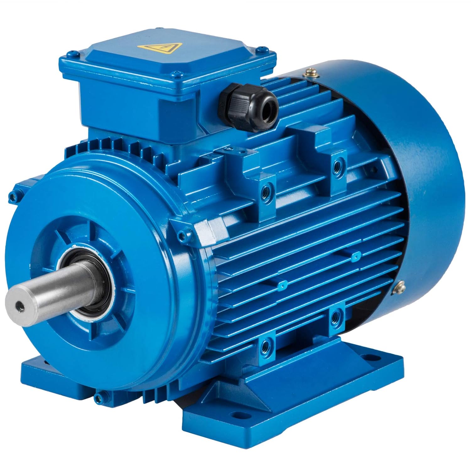
Are there different types of AC motors, and what are their specific applications?
Yes, there are different types of AC motors, each with its own design, characteristics, and applications. The main types of AC motors include:
- Induction Motors: Induction motors are the most commonly used type of AC motor. They are robust, reliable, and suitable for a wide range of applications. Induction motors operate based on the principle of electromagnetic induction. They consist of a stator with stator windings and a rotor with short-circuited conductive bars or coils. The rotating magnetic field produced by the stator windings induces currents in the rotor, creating a magnetic field that interacts with the stator field and generates torque. Induction motors are widely used in industries such as manufacturing, HVAC systems, pumps, fans, compressors, and conveyor systems.
- Synchronous Motors: Synchronous motors are another type of AC motor commonly used in applications that require precise speed control. They operate at synchronous speed, which is determined by the frequency of the AC power supply and the number of motor poles. Synchronous motors have a rotor with electromagnets that are magnetized by direct current, allowing the rotor to lock onto the rotating magnetic field of the stator and rotate at the same speed. Synchronous motors are often used in applications such as industrial machinery, generators, compressors, and large HVAC systems.
- Brushless DC Motors: While the name suggests “DC,” brushless DC motors are actually driven by AC power. They utilize electronic commutation instead of mechanical brushes for switching the current in the motor windings. Brushless DC motors offer high efficiency, low maintenance, and precise control over speed and torque. They are commonly used in applications such as electric vehicles, robotics, computer disk drives, aerospace systems, and consumer electronics.
- Universal Motors: Universal motors are versatile motors that can operate on both AC and DC power. They are designed with a wound stator and a commutator rotor. Universal motors offer high starting torque and can achieve high speeds. They are commonly used in applications such as portable power tools, vacuum cleaners, food mixers, and small appliances.
- Shaded Pole Motors: Shaded pole motors are simple and inexpensive AC motors. They have a single-phase stator and a squirrel cage rotor. Shaded pole motors are characterized by low starting torque and relatively low efficiency. Due to their simple design and low cost, they are commonly used in applications such as small fans, refrigeration equipment, and appliances.
These are some of the main types of AC motors, each with its unique features and applications. The selection of an AC motor type depends on factors such as the required torque, speed control requirements, efficiency, cost, and environmental conditions. Understanding the specific characteristics and applications of each type allows for choosing the most suitable motor for a given application.
editor by CX 2023-11-29
China Professional Bg 775 12V DC Customized Shaft Small Gear Motor vacuum pump for ac
Product Description
| BG 45ZYT DC Brushed Motor | |
| Environmental Conditons | -20ºC~50ºC |
| Lnsulation Clase | B |
| Protection class | IP44 |
| Noise | ≤65dB |
| Number of phases | Single |
| Lifespan | >1000h |
| Electrical Specifications | |||||||||
| Model | RATED LOAD | NO LOAD | STALL | ||||||
| Voltage | Power |
Speed |
Torque | Current | Speed | Current | Torque | Current | |
| V | W | rpm | N.m | A | rpm | A | N.m | A | |
| BG 45775-01 | 12 | 10.4 | 2430 | 0.04 | 1.3 | 3000 | 0.4 | 0.25 | 6.7 |
| BG 45775-02 | 24 | 21.1 | 3850 | 0.05 | 1.25 | 4500 | 0.25 | 0.4 | 8.3 |
| We can also customize products according to customer requirements . | |||||||||
| Planetary Gear Motor Technical Data-BG | ||||||||
| Ratio | 10.2 | 19.2 | 26.9 | 188 | 264 | 721 | 669 | 1911 |
| NO-load speed | 1167 | 700 | 437 | 175 | 98 | 87.5 | 58 | 36 |
| Rated speed(rpm) | 1000 | 600 | 375 | 150 | 83 | 75 | 50 | 31 |
| Rated torque(N.m) | 0.34 | 0.65 | 0.9 | 5.6 | 7.9 | 15 | 15 | 15 |
Established in 1994, HangZhou BG Motor Factory is a professional manufacturer of brushless DC motors, brushed DC motors, planetary gear motors, worm gear motors, Universal motors and AC motors. We have a plant area of 6000 square meters, multiple patent certificates, and we have the independent design and development capabilities and strong technical force, with an annual output of more than 1 million units. Since the beginning of its establishment, BG motor has focused on the overall solution of motors. We manufacture and design motors, provide professional customized services, respond quickly to customer needs, and actively help customers to solve problems. Our motor products are exported to 20 countries, including the United States, Germany, Italy, the United Kingdom, Poland, Slovenia, Switzerland, Sweden, Singapore, South Korea etc.
Our founder, Mr. Sun, has more than 40 years of experience in motor technology, and our other engineers also have more than 15 years of experience, and 60% of our staff have more than 10 years of experience, and we can assure you that the quality of our motors is top notch.
The products cover AGV, underwater robots, robots, sewing machine industry, automobiles, medical equipment, automatic doors, lifting equipment, industrial equipment and have a wide range of applications.
We strive for CHINAMFG in the quality of each product, and we are only a small and sophisticated manufacturer.
Our vision: Drive the world CHINAMFG and make life better!
Q:1.What kind of motors can you provide?
A:At present, we mainly produce brushless DC motors, brush DC motors, AC motors, Universal Motors; the power of the motor is less than 5000W, and the diameter of the motor is not more than 200mm;
Q:2.Can you send me a price list?
A:For all of our motors, they are customized based on different requirements like lifetime, noise,voltage,and shaft etc. The price also varies according to annual quantity. So it’s really difficult for us to provide a price list. If you can share your detailed requirements and annual quantity, we’ll see what offer we can provide.
Q:3.Can l get some samples?
A:It depends. If only a few samples for personal use or replacement, I am afraid it’ll be difficult for us to provide because all of our motors are custom made and no stock available if there are no further needs. If just sample testing before the official order and our MOQ,price and other terms are acceptable,we’d love to provide samples.
Q4:Can you provide OEM or ODM service?
A:Yes,OEM and ODM are both available, we have the professional R&D dept which can provide professional solutions for you.
Q5:Can l visit your factory before we place an order?
A:welcome to visit our factory,wear every pleased if we have the chance to know each other more.
Q:6.What’s the lead time for a regular order?
A:For orders, the standard lead time is 15-20 days and this time can be shorter or longer based on the different model,period and quantity.
| Application: | Universal, Industrial, Household Appliances, Car, Power Tools, Robot Arm |
|---|---|
| Operating Speed: | Low Speed |
| Excitation Mode: | DC |
| Function: | Driving |
| Casing Protection: | Closed Type |
| Number of Poles: | Can Be Choosen |
| Samples: |
US$ 0/Piece
1 Piece(Min.Order) | |
|---|
| Customization: |
Available
|
|
|---|
Where can individuals find reliable resources for learning more about gear motors and their applications?
Individuals seeking to learn more about gear motors and their applications have access to various reliable resources that provide valuable information and insights. Here are some sources where individuals can find reliable information about gear motors:
1. Manufacturer Websites:
Manufacturer websites are a primary source of information about gear motors. Gear motor manufacturers often provide detailed product specifications, application guides, technical documentation, and educational materials on their websites. These resources offer insights into different gear motor types, features, performance characteristics, and application considerations. Manufacturer websites are a reliable and convenient starting point for learning about gear motors.
2. Industry Associations and Organizations:
Industry associations and organizations related to mechanical engineering, automation, and motion control often have resources and publications dedicated to gear motors. These organizations provide technical articles, whitepapers, industry standards, and guidelines related to gear motor design, selection, and application. Examples of such associations include the American Gear Manufacturers Association (AGMA), International Electrotechnical Commission (IEC), and Institute of Electrical and Electronics Engineers (IEEE).
3. Technical Publications and Journals:
Technical publications and journals focused on engineering, robotics, and motion control are valuable sources of in-depth knowledge about gear motors. Publications like IEEE Transactions on Industrial Electronics, Mechanical Engineering magazine, or Motion System Design magazine often feature articles, case studies, and research papers on gear motor technology, advancements, and applications. These publications provide authoritative and up-to-date information from industry experts and researchers.
4. Online Forums and Communities:
Online forums and communities dedicated to engineering, robotics, and automation can be excellent resources for discussions, insights, and practical experiences related to gear motors. Websites like Stack Exchange, engineering-focused subreddits, or specialized forums provide platforms for individuals to ask questions, share knowledge, and engage in discussions with professionals and enthusiasts in the field. Participating in these communities allows individuals to learn from real-world experiences and gain practical insights.
5. Educational Institutions and Courses:
Technical colleges, universities, and vocational training centers often offer courses or programs in mechanical engineering, mechatronics, or automation that cover gear motor fundamentals and applications. These educational institutions provide comprehensive curricula, textbooks, and lecture materials that can serve as reliable resources for individuals interested in learning about gear motors. Additionally, online learning platforms like Coursera, Udemy, or LinkedIn Learning offer courses on topics related to gear motors and motion control.
6. Trade Shows and Exhibitions:
Attending trade shows, exhibitions, and industry conferences related to automation, robotics, or motion control provides opportunities to learn about the latest advancements in gear motor technology. These events often feature product demonstrations, technical presentations, and expert panels where individuals can interact with gear motor manufacturers, industry experts, and other professionals. It’s a great way to stay updated on the latest trends, innovations, and applications of gear motors.
When seeking reliable resources, it’s important to consider the credibility of the source, the expertise of the authors, and the relevance to the specific area of interest. By leveraging these resources, individuals can gain a comprehensive understanding of gear motors and their applications, from basic principles to advanced topics, enabling them to make informed decisions and effectively utilize gear motors in their projects or applications.
Are there environmental benefits to using gear motors in certain applications?
Yes, there are several environmental benefits associated with the use of gear motors in certain applications. Gear motors offer advantages that can contribute to increased energy efficiency, reduced resource consumption, and lower environmental impact. Here’s a detailed explanation of the environmental benefits of using gear motors:
1. Energy Efficiency:
Gear motors can improve energy efficiency in various ways:
- Torque Conversion: Gear reduction allows gear motors to deliver higher torque output while operating at lower speeds. This enables the motor to perform tasks that require high torque, such as lifting heavy loads or driving machinery with high inertia, more efficiently. By matching the motor’s power characteristics to the load requirements, gear motors can operate closer to their peak efficiency, minimizing energy waste.
- Controlled Speed: Gear reduction provides finer control over the motor’s rotational speed. This allows for more precise speed regulation, reducing the likelihood of energy overconsumption and optimizing energy usage.
2. Reduced Resource Consumption:
The use of gear motors can lead to reduced resource consumption and environmental impact:
- Smaller Motor Size: Gear reduction allows gear motors to deliver higher torque with smaller, more compact motors. This reduction in motor size translates to reduced material and resource requirements during manufacturing. It also enables the use of smaller and lighter equipment, which can contribute to energy savings during operation and transportation.
- Extended Motor Lifespan: The gear mechanism in gear motors helps reduce the load and stress on the motor itself. By distributing the load more evenly, gear motors can help extend the lifespan of the motor, reducing the need for frequent replacements and the associated resource consumption.
3. Noise Reduction:
Gear motors can contribute to a quieter and more environmentally friendly working environment:
- Noise Dampening: Gear reduction can help reduce the noise generated by the motor. The gear mechanism acts as a noise dampener, absorbing and dispersing vibrations and reducing overall noise emission. This is particularly beneficial in applications where noise reduction is important, such as residential areas, offices, or noise-sensitive environments.
4. Precision and Control:
Gear motors offer enhanced precision and control, which can lead to environmental benefits:
- Precise Positioning: Gear motors, especially stepper motors and servo motors, provide precise positioning capabilities. This accuracy allows for more efficient use of resources, minimizing waste and optimizing the performance of machinery or systems.
- Optimized Control: Gear motors enable precise control over speed, torque, and movement. This control allows for better optimization of processes, reducing energy consumption and minimizing unnecessary wear and tear on equipment.
In summary, using gear motors in certain applications can have significant environmental benefits. Gear motors offer improved energy efficiency, reduced resource consumption, noise reduction, and enhanced precision and control. These advantages contribute to lower energy consumption, reduced environmental impact, and a more sustainable approach to power transmission and control. When selecting motor systems for specific applications, considering the environmental benefits of gear motors can help promote energy efficiency and sustainability.

Can you explain the advantages of using gear motors in various mechanical systems?
Gear motors offer several advantages when utilized in various mechanical systems. Their unique characteristics make them well-suited for applications that require controlled power transmission, precise speed control, and torque amplification. Here’s a detailed explanation of the advantages of using gear motors:
1. Torque Amplification:
One of the key advantages of gear motors is their ability to amplify torque. By using different gear ratios, gear motors can increase or decrease the output torque from the motor. This torque amplification is crucial in applications that require high torque output, such as lifting heavy loads or operating machinery with high resistance. Gear motors allow for efficient power transmission, enabling the system to handle demanding tasks effectively.
2. Speed Control:
Gear motors provide precise speed control, allowing for accurate and controlled movement in mechanical systems. By selecting the appropriate gear ratio, the rotational speed of the output shaft can be adjusted to match the requirements of the application. This speed control capability ensures that the mechanical system operates at the desired speed, whether it needs to be fast or slow. Gear motors are commonly used in applications such as conveyors, robotics, and automated machinery, where precise speed control is essential.
3. Directional Control:
Another advantage of gear motors is their ability to control the rotational direction of the output shaft. By using different types of gears, such as spur gears, bevel gears, or worm gears, the direction of rotation can be easily changed. This directional control is beneficial in applications that require bidirectional movement, such as in actuators, robotic arms, and conveyors. Gear motors offer reliable and efficient directional control, contributing to the versatility and functionality of mechanical systems.
4. Efficiency and Power Transmission:
Gear motors are known for their high efficiency in power transmission. The gear system helps distribute the load across multiple gears, reducing the strain on individual components and minimizing power losses. This efficient power transmission ensures that the mechanical system operates with optimal energy utilization and minimizes wasted power. Gear motors are designed to provide reliable and consistent power transmission, resulting in improved overall system efficiency.
5. Compact and Space-Saving Design:
Gear motors are compact in size and offer a space-saving solution for mechanical systems. By integrating the motor and gear system into a single unit, gear motors eliminate the need for additional components and reduce the overall footprint of the system. This compact design is especially beneficial in applications with limited space constraints, allowing for more efficient use of available space while still delivering the necessary power and functionality.
6. Durability and Reliability:
Gear motors are designed to be robust and durable, capable of withstanding demanding operating conditions. The gear system helps distribute the load, reducing the stress on individual gears and increasing overall durability. Additionally, gear motors are often constructed with high-quality materials and undergo rigorous testing to ensure reliability and longevity. This makes gear motors well-suited for continuous operation in industrial and commercial applications, where reliability is crucial.
By leveraging the advantages of torque amplification, speed control, directional control, efficiency, compact design, durability, and reliability, gear motors provide a reliable and efficient solution for various mechanical systems. They are widely used in industries such as robotics, automation, manufacturing, automotive, and many others, where precise and controlled mechanical power transmission is essential.
editor by CX 2023-11-17
China Good quality Planetary Winch Drive Slew Gear Housing Reducer Gearbox Small Wind Turbine Hollow Shaft High Torque Motors Bevel 2 Speed Multi Stage Inline Epicyclic Hydraulic supplier
Product Description
Planetary Winch Drive Slew Gear Housing Reducer Gearbox Small Wind Turbine Hollow Shaft High Torque Motors Bevel 2 Speed Multi Stage Inline Epicyclic Hydraulic
1. The wide and comprehensive range of N series for industrial applications
2. Low-speed shaft design: Cylindrical with key, splined, hollow with shrink disc or splined hollow shaft
3. Rigid and precise nodular cast iron casing
4. Low noise running, high manufacturing quality standard
5. High and reliable performance, load capacity and low-speed shaft bearing
Please click here for more types!
Application
Our factory
Related Products
For more reducers and mechanical accessories, please click here to view
| Application: | Motor, Electric Cars, Motorcycle, Machinery, Marine, Toy, Agricultural Machinery, Car |
|---|---|
| Function: | Distribution Power, Speed Changing, Speed Reduction |
| Layout: | Wrom |
| Hardness: | Hardened Tooth Surface |
| Installation: | Planetary |
| Step: | Planetary |

What Is a Gear Motor?
A gear motor is an electric motor coupled with a gear train. It uses either DC or AC power to achieve its purpose. The primary benefit of a gear reducer is its ability to multiply torque while maintaining a compact size. The trade-off of this additional torque comes in the form of a reduced output shaft speed and overall efficiency. However, proper gear technology and ratios provide optimum output and speed profiles. This type of motor unlocks the full potential of OEM equipment.
Inertial load
Inertial load on a gear motor is the amount of force a rotating device produces due to its inverse square relationship with its inertia. The greater the inertia, the less torque can be produced by the gear motor. However, if the inertia is too high, it can cause problems with positioning, settling time, and controlling torque and velocity. Gear ratios should be selected for optimal power transfer.
The duration of acceleration and braking time of a gear motor depends on the type of driven load. An inertia load requires longer acceleration time whereas a friction load requires breakaway torque to start the load and maintain it at its desired speed. Too short a time period can cause excessive gear loading and may result in damaged gears. A safe approach is to disconnect the load when power is disconnected to prevent inertia from driving back through the output shaft.
Inertia is a fundamental concept in the design of motors and drive systems. The ratio of mass and inertia of a load to a motor determines how well the motor can control its speed during acceleration or deceleration. The mass moment of inertia, also called rotational inertia, is dependent on the mass, geometry, and center of mass of an object.
Applications
There are many applications of gear motors. They provide a powerful yet efficient means of speed and torque control. They can be either AC or DC, and the two most common motor types are the three-phase asynchronous and the permanent magnet synchronous servomotor. The type of motor used for a given application will determine its cost, reliability, and complexity. Gear motors are typically used in applications where high torque is required and space or power constraints are significant.
There are two types of gear motors. Depending on the ratio, each gear has an output shaft and an input shaft. Gear motors use hydraulic pressure to produce torque. The pressure builds on one side of the motor until it generates enough torque to power a rotating load. This type of motors is not recommended for applications where load reversals occur, as the holding torque will diminish with age and shaft vibration. However, it can be used for precision applications.
The market landscape shows the competitive environment of the gear motor industry. This report also highlights key items, income and value creation by region and country. The report also examines the competitive landscape by region, including the United States, China, India, the GCC, South Africa, Brazil, and the rest of the world. It is important to note that the report contains segment-specific information, so that readers can easily understand the market potential of the geared motors market.
Size
The safety factor, or SF, of a gear motor is an important consideration when selecting one for a particular application. It compensates for the stresses placed on the gearing and enables it to run at maximum efficiency. Manufacturers provide tables detailing typical applications, with multiplication factors for duty. A gear motor with a SF of three or more is suitable for difficult applications, while a gearmotor with a SF of one or two is suitable for relatively easy applications.
The global gear motor market is highly fragmented, with numerous small players catering to various end-use industries. The report identifies various industry trends and provides comprehensive information on the market. It outlines historical data and offers valuable insights on the industry. The report also employs several methodologies and approaches to analyze the market. In addition to providing historical data, it includes detailed information by market segment. In-depth analysis of market segments is provided to help identify which technologies will be most suitable for which applications.
Cost
A gear motor is an electric motor that is paired with a gear train. They are available in AC or DC power systems. Compared to conventional motors, gear reducers can maximize torque while maintaining compact dimensions. But the trade-off is the reduced output shaft speed and overall efficiency. However, when used correctly, a gear motor can produce optimal output and mechanical fit. To understand how a gear motor works, let’s look at two types: right-angle geared motors and inline geared motors. The first two types are usually used in automation equipment and in agricultural and medical applications. The latter type is designed for rugged applications.
In addition to its efficiency, DC gear motors are space-saving and have low energy consumption. They can be used in a number of applications including money counters and printers. Automatic window machines and curtains, glass curtain walls, and banknote vending machines are some of the other major applications of these motors. They can cost up to 10 horsepower, which is a lot for an industrial machine. However, these are not all-out expensive.
Electric gear motors are versatile and widely used. However, they do not work well in applications requiring high shaft speed and torque. Examples of these include conveyor drives, frozen beverage machines, and medical tools. These applications require high shaft speed, so gear motors are not ideal for these applications. However, if noise and other problems are not a concern, a motor-only solution may be the better choice. This way, you can use a single motor for multiple applications.
Maintenance
Geared motors are among the most common equipment used for drive trains. Proper maintenance can prevent damage and maximize their efficiency. A guide to gear motor maintenance is available from WEG. To prevent further damage, follow these maintenance steps:
Regularly check electrical connections. Check for loose connections and torque them to the recommended values. Also, check the contacts and relays to make sure they are not tangled or damaged. Check the environment around the gear motor to prevent dust from clogging the passageway of electric current. A proper maintenance plan will help you identify problems and extend their life. The manual will also tell you about any problems with the gearmotor. However, this is not enough – it is important to check the condition of the gearbox and its parts.
Conduct visual inspection. The purpose of visual inspection is to note any irregularities that may indicate possible problems with the gear motor. A dirty motor may be an indication of a rough environment and a lot of problems. You can also perform a smell test. If you can smell a burned odor coming from the windings, there may be an overheating problem. Overheating can cause the windings to burn and damage.
Reactive maintenance is the most common method of motor maintenance. In this type of maintenance, you only perform repairs if the motor stops working due to a malfunction. Regular inspection is necessary to avoid unexpected motor failures. By using a logbook to document motor operations, you can determine when it is time to replace the gear motor. In contrast to preventive maintenance, reactive maintenance requires no regular tests or services. However, it is recommended to perform inspections every six months.
editor by CX 2023-11-14
China manufacturer CHINAMFG Speed Control Micro AC Gear Parallel Shaft Gear Reducer Motor vacuum pump connector
Product Description
CHINAMFG gear motor is ideal drive for all kinds of inudstrial automation products for both industrial and commercial application.
What you can be provide by us is steady quality products(quite and efficient performance gear motor) and engineering solution.
We produce AC gear motor,right angle gear motor,DC gear motor,DC brushless gear motor,high precision planetary gear motor,worm gear motor,drum motor and spring operation mechanism used gear motor,etc.
1)End cover and housing of motor is made of die-casting Aluminum,which is high precision,high strength and light weight.
2)The stator consists of silicon steel sheet stator core,copper coil,and insulating material,etc.
3)The rotor consists of laminated silicon steel sheet and aluminum cast conductor.
4)The rotor shaft is made of high-performance medium carbon alloy steel and processed by special technics.There are round shaft and gear shaft.
5)The bearing and oil seal is selected from CHINAMFG brand to ensure good running performance and sealing effect.
6)The wire is made from high temperature resistant and flame retardant material.
Should you any questions,please feel free to contact Ms Susan Liu.
Please leave message or send inquiry.I will be back to you asap.
Select method
RK gear motor Series , IK gear motor Series, Constant speed motor type, Speed control motor type, Three phase 220V motor type,
Three phase 380V motor type,Fan motor type,Brake motor type
STHangZhouRD CHINAMFG CODE MEANING (FOR AC SMALL GEAR MOTOR)
1.Shell type 2 means 60mm,3 means 70mm,4 means 80mm,5 means 90mm,6 means 100mm(the dia of the motor shell)
2.motor type code IK means induction motor( note:single phase motor have 4 leading wire ,all 3 phase motors are induction
motor,60mm motor does not have induction type , ),RK means reversible motor(single phase motor have 3 leading wire)
3.motor power code 6 means 6W,15 means 15W,20means 20W,25 means 25W,40 means 40W,……200 means 200W
4.speed control type code with R means speed control type , without R means fixed speed
5.motor shaft code GN means tooth shaft ,A1 means circular shaft with flat face, A2 means circular shaft with key slot
6.voltage code A means 110V,C means 220V,S means 3ph220V,S3 means 3ph380V,SS3 means 3ph220V/380V
7.Terminal box code L means leading wire 450mm,TT means terminal box with terminal block ,TC means terminal box with capacitor inside
8. T-box/leadwire direction A means left of shaft ,B means down of shaft,C means right of shaft, D means CHINAMFG of shaft, See from the sight of shaft ,default direction is B,see attachment
9.Leadwire of T-box direction U: up D: down L : left R: right ,See from the front sight of terminal box , default direction is D ,See attached
10.Thermal protector code P means thermal protector, without means without thermal protector
11.cooling fan code F means cooling fan, without means without cooling fan ,M means with magnet brake,FM means with magnet brake and cooling fan
12.gearbox type code 2 means 60mm,3 means 70mm,4 means 80mm,5 means 90mm,6 means 104mm(the flange of the square gearbox shell)
13.gearbox flange type code GN means square type gearbox ,GS means ear flange type gearbox
14.speed ratio code 3,5,6,7.5,10,12.5,15,18,20,25,30,36,40,50,60,75,90,100,120,150,180,200,250,300,500,750
15.bearing type code K means standard ball bearing , RT means right angle CHINAMFG shaft , RC means right angle hollow shaft
16.shaft dia code G8 means 8mm dia shaft,G10 means 10mm dia shaft, G12 means 12mm dia shaft, G15 means 15mm dia shaft
17.connection screw code L means screw hole , T means through hole type
18.key slot code K3 means 3*3*18mm ,K4 means 4*4*25 key K5 means 5*5*25 key ,F1 means flat face1*25 , F2 means flat face 1*20
| Basic tech data: | ||
| Motor type: AC gear motor | Insulation Class:E | |
| Motor material:Aluminum ,Copper,Steel | IP grade:IP44 | |
| Rotation:CW/CCW reversible | Working style:S1 | |
| Frequency: 50Hz/60Hz | Operating temperature range: -10 °C~ | Operating relative humidity: 95% Below |
Motor Specification and Tech Data
| TYPE | Rated Power | Nominal voltage | Noload Speed | Rated Speed | Rated Current | Rated Torque | Stall Current | Stall Torque |
| W | V | rpm | rpm | A | N.m | A | N.m | |
| 2RK6A-CA2 | 6 | 1ph220V | 1450 | 1200 | 0.12 | 0.049 | 0.2184 | 0.09 |
| 2RK6RA-CA2 | 6 | 1ph220V | 1450 | 1200 | 0.12 | 0.049 | 0.2184 | 0.09 |
| 2RK10A-CA2 | 10 | 1ph220V | 1450 | 1200 | 0.15 | 0.082 | 0.273 | 0.15 |
| 2RK10RA-CA2 | 10 | 1ph220V | 1450 | 1200 | 0.15 | 0.082 | 0.273 | 0.15 |
| 3RK15A-CA2 | 15 | 1ph220V | 1450 | 1200 | 0.20 | 0.125 | 0.364 | 0.23 |
| 3RK15RA-CA2 | 15 | 1ph220V | 1450 | 1200 | 0.20 | 0.125 | 0.364 | 0.23 |
| 3RK20RA-CA2 | 20 | 1ph220V | 1450 | 1200 | 0.25 | 0.182 | 0.455 | 0.33 |
| 3RK20RA-CA2 | 20 | 1ph220V | 1450 | 1200 | 0.25 | 0.182 | 0.455 | 0.33 |
| 4RK25A-CA2 | 25 | 1ph220V | 1450 | 1200 | 0.30 | 0.195 | 0.546 | 0.35 |
| 4RK25RA-CA2 | 25 | 1ph220V | 1450 | 1200 | 0.30 | 0.195 | 0.546 | 0.35 |
| 4RK30A-CA2 | 30 | 1ph220V | 1450 | 1200 | 0.35 | 0.235 | 0.637 | 0.43 |
| 4RK30RA-CA2 | 30 | 1ph220V | 1450 | 1200 | 0.35 | 0.235 | 0.637 | 0.43 |
| 4RK40A-CA2 | 40 | 1ph220V | 1450 | 1200 | 0.45 | 0.30 | 0.819 | 0.55 |
| 4RK40RA-CA2 | 40 | 1ph220V | 1450 | 1200 | 0.45 | 0.30 | 0.819 | 0.55 |
| 5RK40A-CA1 | 40 | 1ph220V | 1450 | 1300 | 0.45 | 0.30 | 0.819 | 0.55 |
| 5RK40RA-CA1 | 40 | 1ph220V | 1450 | 1300 | 0.45 | 0.30 | 0.819 | 0.55 |
| 5RK60A-CFA1 | 60 | 1ph220V | 1450 | 1300 | 0.55 | 0.45 | 1.001 | 0.82 |
| 5RK60RA-CFA1 | 60 | 1ph220V | 1450 | 1300 | 0.55 | 0.45 | 1.001 | 0.82 |
| 5RK90A-CFA1 | 90 | 1ph220V | 1450 | 1300 | 0.95 | 0.68 | 1.729 | 1.24 |
| 5RK90RA-CFA1 | 90 | 1ph220V | 1450 | 1300 | 0.95 | 0.68 | 1.729 | 1.24 |
| 5RK120A-CFA1 | 120 | 1ph220V | 1450 | 1300 | 1.15 | 0.90 | 2.093 | 1.64 |
| 5RK120RA-CFA1 | 120 | 1ph220V | 1450 | 1300 | 1.15 | 0.90 | 2.093 | 1.64 |
| 6RK120A-CFA1 | 120 | 1ph220V | 1450 | 1300 | 1.2 | 0.90 | 2.184 | 1.64 |
| 6RK120RA-CFA1 | 120 | 1ph220V | 1450 | 1300 | 1.2 | 0.90 | 2.184 | 1.64 |
| 6RK140A-CFA1 | 140 | 1ph220V | 1450 | 1300 | 1.4 | 1.05 | 2.548 | 1.91 |
| 6RK140RA-CFA1 | 140 | 1ph220V | 1450 | 1300 | 1.4 | 1.05 | 2.548 | 1.91 |
| 6RK160A-CFA1 | 160 | 1ph220V | 1450 | 1300 | 1.6 | 1.20 | 2.912 | 2.18 |
| 6RK160RA-CFA1 | 160 | 1ph220V | 1450 | 1300 | 1.6 | 1.20 | 2.912 | 2.18 |
| 6RK180A-CFA1 | 180 | 1ph220V | 1450 | 1300 | 1.8 | 1.35 | 3.276 | 2.46 |
| 6RK180RA-CFA1 | 180 | 1ph220V | 1450 | 1300 | 1.8 | 1.35 | 3.276 | 2.46 |
| 6RK200A-CFA1 | 200 | 1ph220V | 1450 | 1300 | 1.9 | 1.50 | 3.458 | 2.73 |
| 6RK200RA-CFA1 | 200 | 1ph220V | 1450 | 1300 | 1.9 | 1.50 | 3.458 | 2.73 |
| 6RK250A-CFA1 | 250 | 1ph220V | 1450 | 1300 | 2.1 | 1.65 | 3.822 | 3.00 |
| 6RK250RA-CFA1 | 250 | 1ph220V | 1450 | 1300 | 2.1 | 1.65 | 3.822 | 3.00 |
| Application: | Industrial |
|---|---|
| Speed: | Constant Speed |
| Number of Stator: | Three-Phase |
| Function: | Driving |
| Casing Protection: | Protection Type |
| Number of Poles: | 4 |
| Samples: |
US$ 30/Piece
1 Piece(Min.Order) | |
|---|
| Customization: |
Available
|
|
|---|
How is the efficiency of a gear motor measured, and what factors can affect it?
The efficiency of a gear motor is a measure of how effectively it converts electrical input power into mechanical output power. It indicates the motor’s ability to minimize losses and maximize its energy conversion efficiency. The efficiency of a gear motor is typically measured using specific methods, and several factors can influence it. Here’s a detailed explanation:
Measuring Efficiency:
The efficiency of a gear motor is commonly measured by comparing the mechanical output power (Pout) to the electrical input power (Pin). The formula to calculate efficiency is:
Efficiency = (Pout / Pin) * 100%
The mechanical output power can be determined by measuring the torque (T) produced by the motor and the rotational speed (ω) at which it operates. The formula for mechanical power is:
Pout = T * ω
The electrical input power can be measured by monitoring the current (I) and voltage (V) supplied to the motor. The formula for electrical power is:
Pin = V * I
By substituting these values into the efficiency formula, the efficiency of the gear motor can be calculated as a percentage.
Factors Affecting Efficiency:
Several factors can influence the efficiency of a gear motor. Here are some notable factors:
- Friction and Mechanical Losses: Friction between moving parts, such as gears and bearings, can result in mechanical losses and reduce the overall efficiency of the gear motor. Minimizing friction through proper lubrication, high-quality components, and efficient design can help improve efficiency.
- Gearing Efficiency: The design and quality of the gears used in the gear motor can impact its efficiency. Gear trains can introduce mechanical losses due to gear meshing, misalignment, or backlash. Using well-designed gears with proper tooth profiles and minimizing gear train losses can improve efficiency.
- Motor Type and Construction: Different types of motors (e.g., brushed DC, brushless DC, AC induction) have varying efficiency characteristics. Motor construction, such as the quality of magnetic materials, winding resistance, and rotor design, can also affect efficiency. Choosing motors with higher efficiency ratings can improve overall gear motor efficiency.
- Electrical Losses: Electrical losses, such as resistive losses in motor windings or in the motor drive circuitry, can reduce efficiency. Minimizing resistance, optimizing motor drive electronics, and using efficient control algorithms can help mitigate electrical losses.
- Load Conditions: The operating conditions and load characteristics placed on the gear motor can impact its efficiency. Heavy loads, high speeds, or frequent acceleration and deceleration can increase losses and reduce efficiency. Matching the gear motor’s specifications to the application requirements and optimizing load conditions can improve efficiency.
- Temperature: Elevated temperatures can significantly affect the efficiency of a gear motor. Excessive heat can increase resistive losses, reduce lubrication effectiveness, and affect the magnetic properties of motor components. Proper cooling and thermal management techniques are essential to maintain optimal efficiency.
By considering these factors and implementing measures to minimize losses and optimize performance, the efficiency of a gear motor can be enhanced. Manufacturers often provide efficiency specifications for gear motors, allowing users to select motors that best meet their efficiency requirements for specific applications.
What are some common challenges or issues associated with gear motors, and how can they be addressed?
Gear motors, like any mechanical system, can face certain challenges or issues that may affect their performance, reliability, or longevity. However, many of these challenges can be addressed through proper design, maintenance, and operational practices. Here are some common challenges associated with gear motors and potential solutions:
1. Gear Wear and Failure:
Over time, gears in a gear motor can experience wear, resulting in decreased performance or even failure. The following measures can address this challenge:
- Proper Lubrication: Regular lubrication with the appropriate lubricant can minimize friction and wear between gear teeth. It is essential to follow manufacturer recommendations for lubrication intervals and use high-quality lubricants suitable for the specific gear motor.
- Maintenance and Inspection: Routine maintenance and periodic inspections can help identify early signs of gear wear or damage. Timely replacement of worn gears or components can prevent further damage and ensure the gear motor’s optimal performance.
- Material Selection: Choosing gears made from durable and wear-resistant materials, such as hardened steel or specialized alloys, can increase their lifespan and resistance to wear.
2. Backlash and Inaccuracy:
Backlash, as discussed earlier, can introduce inaccuracies in gear motor systems. The following approaches can help address this issue:
- Anti-Backlash Gears: Using anti-backlash gears, which are designed to minimize or eliminate backlash, can significantly reduce inaccuracies caused by gear play.
- Tight Manufacturing Tolerances: Ensuring precise manufacturing tolerances during gear production helps minimize backlash and improve overall accuracy.
- Backlash Compensation: Implementing control algorithms or mechanisms to compensate for backlash can help mitigate its effects and improve the accuracy of the gear motor.
3. Noise and Vibrations:
Gear motors can generate noise and vibrations during operation, which may be undesirable in certain applications. The following strategies can help mitigate this challenge:
- Noise Dampening: Incorporating noise-dampening features, such as vibration-absorbing materials or isolation mounts, can reduce noise and vibrations transmitted from the gear motor to the surrounding environment.
- Quality Gears and Bearings: Using high-quality gears and bearings can minimize vibrations and noise generation. Precision-machined gears and well-maintained bearings help ensure smooth operation and reduce unwanted noise.
- Proper Alignment: Ensuring accurate alignment of gears, shafts, and other components reduces the likelihood of noise and vibrations caused by misalignment. Regular inspections and adjustments can help maintain optimal alignment.
4. Overheating and Thermal Management:
Heat buildup can be a challenge in gear motors, especially during prolonged or heavy-duty operation. Effective thermal management techniques can address this issue:
- Adequate Ventilation: Providing proper ventilation and airflow around the gear motor helps dissipate heat. This can involve designing cooling fins, incorporating fans or blowers, or ensuring sufficient clearance for air circulation.
- Heat Dissipation Materials: Using heat-dissipating materials, such as aluminum or copper, in motor housings or heat sinks can improve heat dissipation and prevent overheating.
- Monitoring and Control: Implementing temperature sensors and thermal protection mechanisms allows for real-time monitoring of the gear motor’s temperature. If the temperature exceeds safe limits, the motor can be automatically shut down or adjusted to prevent damage.
5. Load Variations and Shock Loads:
Unexpected load variations or shock loads can impact the performance and durability of gear motors. The following measures can help address this challenge:
- Proper Sizing and Selection: Choosing gear motors with appropriate torque and load capacity ratings for the intended application helps ensure they can handle expected load variations and occasional shock loads without exceeding their limits.
- Shock Absorption: Incorporating shock-absorbing mechanisms, such as dampers or resilient couplings, can help mitigate the effects of sudden load changes or impacts on the gear motor.
- Load Monitoring: Implementing load monitoring systems or sensors allows for real-time monitoring of load variations. This information can be used to adjust operation or trigger protective measures when necessary.
By addressing these common challenges associated with gear motors through appropriate design considerations, regular maintenance, and operational practices, it is possible to enhance their performance, reliability, and longevity.

How does the gearing mechanism in a gear motor contribute to torque and speed control?
The gearing mechanism in a gear motor plays a crucial role in controlling torque and speed. By utilizing different gear ratios and configurations, the gearing mechanism allows for precise manipulation of these parameters. Here’s a detailed explanation of how the gearing mechanism contributes to torque and speed control in a gear motor:
The gearing mechanism consists of multiple gears with varying sizes, tooth configurations, and arrangements. Each gear in the system engages with another gear, creating a mechanical connection. When the motor rotates, it drives the rotation of the first gear, which then transfers the motion to subsequent gears, ultimately resulting in the output shaft’s rotation.
Torque Control:
The gearing mechanism in a gear motor enables torque control through the principle of mechanical advantage. The gear system utilizes gears with different numbers of teeth, known as gear ratio, to adjust the torque output. When a smaller gear (pinion) engages with a larger gear (gear), the pinion rotates faster than the gear but exerts more force or torque. This results in torque amplification, allowing the gear motor to deliver higher torque at the output shaft while reducing the rotational speed. Conversely, if a larger gear engages with a smaller gear, torque reduction occurs, resulting in higher rotational speed at the output shaft.
By selecting the appropriate gear ratio, the gearing mechanism effectively adjusts the torque output of the gear motor to match the requirements of the application. This torque control capability is essential in applications that demand high torque for heavy lifting or overcoming resistance, as well as applications that require lower torque but higher rotational speed.
Speed Control:
The gearing mechanism also contributes to speed control in a gear motor. The gear ratio determines the relationship between the rotational speed of the input shaft (driven by the motor) and the output shaft. When a gear motor has a higher gear ratio (more teeth on the driven gear compared to the driving gear), it reduces the output speed while increasing the torque. Conversely, a lower gear ratio increases the output speed while reducing the torque.
By choosing the appropriate gear ratio, the gearing mechanism allows for precise speed control in a gear motor. This is particularly useful in applications that require specific speed ranges or variations, such as conveyor systems, robotic movements, or machinery that needs to operate at different speeds for different tasks. The speed control capability of the gearing mechanism enables the gear motor to match the desired speed requirements of the application accurately.
In summary, the gearing mechanism in a gear motor contributes to torque and speed control by utilizing different gear ratios and configurations. It enables torque amplification or reduction, depending on the gear arrangement, allowing the gear motor to deliver the required torque output. Additionally, the gear ratio also determines the relationship between the rotational speed of the input and output shafts, providing precise speed control. These torque and speed control capabilities make gear motors versatile and suitable for a wide range of applications in various industries.
editor by CX 2023-10-20
China A58SW31ZYS 12-24V worm gear motor 7-470 rpm Reversed Dc Motor electric Dc Motor Double Shaft For Diy Experiment Brin motor electric
Warranty: Other
Model Variety: A58SW31ZYS
Use: BOAT, Vehicle, Electrical Bicycle, Enthusiast, Residence Equipment
Type: Gear MOTOR
Torque: 3.4-70kg.cm
Building: Everlasting Magnet
Commutation: Brush
Protect Attribute: Entirely Enclosed
Speed(RPM): 5-470RPM
Constant Present(A): ≤0.6A / ≤1.6A
Efficiency: IE 1
Merchandise Identify: Bringsmart A58SW31ZYS DC Motor Electric DC Motor 12V DC Motor
Certification: CCC,ce,RoHS
Packaging Specifics: Interior Packaging: High Quality Bubble bags Outdoors packing: Secure Kraft Cartons
| Brand Name | BringSmart |
| Main Product | DC Motor, AC Motor, DC Linear Actuator view much more |
| OEM | Accepted |
| Delivery Time | Within fifteen times |
Benefits of a Planetary Motor
Besides being one of the most efficient forms of a drive, a Planetary Motor also offers a great number of other benefits. These features enable it to create a vast range of gear reductions, as well as generate higher torques and torque density. Let’s take a closer look at the benefits this mechanism has to offer. To understand what makes it so appealing, we’ll explore the different types of planetary systems.
Solar gear
The solar gear on a planetary motor has two distinct advantages. It produces less noise and heat than a helical gear. Its compact footprint also minimizes noise. It can operate at high speeds without sacrificing efficiency. However, it must be maintained with constant care to operate efficiently. Solar gears can be easily damaged by water and other debris. Solar gears on planetary motors may need to be replaced over time.
A planetary gearbox is composed of a sun gear and two or more planetary ring and spur gears. The sun gear is the primary gear and is driven by the input shaft. The other two gears mesh with the sun gear and engage the stationary ring gear. The three gears are held together by a carrier, which sets the spacing. The output shaft then turns the planetary gears. This creates an output shaft that rotates.
Another advantage of planetary gears is that they can transfer higher torques while being compact. These advantages have led to the creation of solar gears. They can reduce the amount of energy consumed and produce more power. They also provide a longer service life. They are an excellent choice for solar-powered vehicles. But they must be installed by a certified solar energy company. And there are other advantages as well. When you install a solar gear on a planetary motor, the energy produced by the sun will be converted to useful energy.
A solar gear on a planetary motor uses a solar gear to transmit torque from the sun to the planet. This system works on the principle that the sun gear rotates at the same rate as the planet gears. The sun gear has a common design modulus of -Ns/Np. Hence, a 24-tooth sun gear equals a 3-1/2 planet gear ratio. When you consider the efficiency of solar gears on planetary motors, you will be able to determine whether the solar gears are more efficient.
Sun gear
The mechanical arrangement of a planetary motor comprises of two components: a ring gear and a sun gear. The ring gear is fixed to the motor’s output shaft, while the sun gear rolls around and orbits around it. The ring gear and sun gear are linked by a planetary carrier, and the torque they produce is distributed across their teeth. The planetary structure arrangement also reduces backlash, and is critical to achieve a quick start and stop cycle.
When the two planetary gears rotate independently, the sun gear will rotate counterclockwise and the ring-gear will turn in the same direction. The ring-gear assembly is mounted in a carrier. The carrier gear and sun gear are connected to each other by a shaft. The planetary gears and sun gear rotate around each other on the ring-gear carrier to reduce the speed of the output shaft. The planetary gear system can be multiplied or staged to obtain a higher reduction ratio.
A planetary gear motor mimics the planetary rotation system. The input shaft turns a central gear, known as the sun gear, while the planetary gears rotate around a stationary sun gear. The motor’s compact design allows it to be easily mounted to a vehicle, and its low weight makes it ideal for small vehicles. In addition to being highly efficient, a planetary gear motor also offers many other benefits.
A planetary gearbox uses a sun gear to provide torque to the other gears. The planet pinions mesh with an internal tooth ring gear to generate rotation. The carrier also acts as a hub between the input gear and output shaft. The output shaft combines these two components, giving a higher torque. There are three types of planetary gearboxes: the sun gear and a wheel drive planetary gearbox.
Planetary gear
A planetary motor gear works by distributing rotational force along a separating plate and a cylindrical shaft. A shock-absorbing device is included between the separating plate and cylindrical shaft. This depressed portion prevents abrasion wear and foreign particles from entering the device. The separating plate and shaft are positioned coaxially. In this arrangement, the input shaft and output shaft are rotated relative to one another. The rotatable disc absorbs the impact.
Another benefit of a planetary motor gear is its efficiency. Planetary motor gears are highly efficient at transferring power, with 97% of the input energy being transferred to the output. They can also have high gear ratios, and offer low noise and backlash. This design also allows the planetary gearbox to work with electric motors. In addition, planetary gears also have a long service life. The efficiency of planetary gears is due in part to the large number of teeth.
Other benefits of a planetary motor gear include the ease of changing ratios, as well as the reduced safety stock. Unlike other gears, planetary gears don’t require special tools for changing ratios. They are used in numerous industries, and share parts across multiple sizes. This means that they are cost-effective to produce and require less safety stock. They can withstand high shock and wear, and are also compact. If you’re looking for a planetary motor gear, you’ve come to the right place.
The axial end surface of a planetary gear can be worn down by abrasion with a separating plate. In addition, foreign particles may enter the planetary gear device. These particles can damage the gears or even cause noise. As a result, you should check planetary gears for damage and wear. If you’re looking for a gear, make sure it has been thoroughly tested and installed by a professional.
Planetary gearbox
A planetary motor and gearbox are a common combination of electric and mechanical power sources. They share the load of rotation between multiple gear teeth to increase the torque capacity. This design is also more rigid, with low backlash that can be as low as one or two arc minutes. The advantages of a planetary gearmotor over a conventional electric motor include compact size, high efficiency, and less risk of gear failure. Planetary gear motors are also more reliable and durable than conventional electric motors.
A planetary gearbox is designed for a single stage of reduction, or a multiple-stage unit can be built with several individual cartridges. Gear ratios may also be selected according to user preference, either to face mount the output stage or to use a 5mm hex shaft. For multi-stage planetary gearboxes, there are a variety of different options available. These include high-efficiency planetary gearboxes that achieve a 98% efficiency at single reduction. In addition, they are noiseless, and reduce heat loss.
A planetary gearbox may be used to increase torque in a robot or other automated system. There are different types of planetary gear sets available, including gearboxes with sliding or rolling sections. When choosing a planetary gearset, consider the environment and other factors such as backlash, torque, and ratio. There are many advantages to a planetary gearbox and the benefits and drawbacks associated with it.
Planetary gearboxes are similar to those in a solar system. They feature a central sun gear in the middle, two or more outer gears, and a ring gear at the output. The planetary gears rotate in a ring-like structure around a stationary sun gear. When the gears are engaged, they are connected by a carrier that is fixed to the machine’s shaft.
Planetary gear motor
Planetary gear motors reduce the rotational speed of an armature by one or more times. The reduction ratio depends on the structure of the planetary gear device. The planetary gear device has an output shaft and an armature shaft. A separating plate separates the two. The output shaft moves in a circular pattern to turn the pinion 3. When the pinion rotates to the engagement position, it is engaged with the ring gear 4. The ring gear then transmits the rotational torque to the armature shaft. The result is that the engine cranks up.
Planetary gear motors are cylindrical in shape and are available in various power levels. They are typically made of steel or brass and contain multiple gears that share the load. These motors can handle massive power transfers. The planetary gear drive, on the other hand, requires more components, such as a sun’s gear and multiple planetary gears. Consequently, it may not be suitable for all types of applications. Therefore, the planetary gear drive is generally used for more complex machines.
Brush dusts from the electric motor may enter the planetary gear device and cause it to malfunction. In addition, abrasion wear on the separating plate can affect the gear engagement of the planetary gear device. If this occurs, the gears will not engage properly and may make noise. In order to prevent such a situation from occurring, it is important to regularly inspect planetary gear motors and their abrasion-resistant separating plates.
Planetary gear motors come in many different power levels and sizes. These motors are usually cylindrical in shape and are made of steel, brass, plastic, or a combination of both materials. A planetary gear motor can be used in applications where space is an issue. This motor also allows for low gearings in small spaces. The planetary gearing allows for large amounts of power transfer. The output shaft size is dependent on the gear ratio and the motor speed.
editor by czh 2023-02-17